EasyManua.ls Logo

Panasonic CU-PS12PKV User Manual

Panasonic CU-PS12PKV
116 pages
To Next Page IconTo Next Page
Page #1 background imageLoading...
Page #1 background image
© Panasonic Corporation 2013
Order No: PAPAMY1307113CE
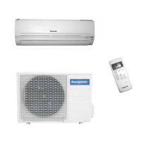
Indoor Unit Outdoor Unit
CS-PS9PKV
CS-PS12PKV
CS-PS18PKV
CS-PS24PKV
CU-PS9PKV
CU-PS12PKV
CU-PS18PKV
CU-PS24PKV
Destination
Panama
Columbia
Ecuador
Caribbean Islands
Trinidad & Tobago
PRECAUTION OF LOW TEMPERATURE
In order to avoid frostbit, be assured of no refrigerant leakage during the installation or repairing of refrigerant circuit.
WARNING
This service information is designed for experienced repair technicians only and is not designed for use by the general public.
It does not contain warnings or cautions to advise non-technical individuals of potential dangers in attempting to service a product.
Products powered by electricity should be serviced or repaired only by experienced professional technicians. Any attempt to
service or repair the products dealt with in this service information by anyone else could result in serious injury or death.

Table of Contents

Questions and Answers:

Panasonic CU-PS12PKV Specifications

General IconGeneral
Energy Efficiency Rating5 Star
Compressor TypeRotary
RefrigerantR32
Weight (Indoor Unit)9 kg
TypeSplit AC
Cooling Capacity3.5 kW
Outdoor Unit Dimensions (W x H x D)780 x 540 x 265 mm

Summary

Safety Precautions

Specification

Location of Controls and Components

Indoor Unit

Shows locations of controls and indicators on the indoor unit.

Outdoor Unit

Shows locations of components on the outdoor unit.

Remote Control

Illustrates the layout and functions of the remote control.

Dimensions

Indoor Unit

Detailed dimensions and mounting hole layout for indoor units.

Outdoor Unit

Shows dimensions and installation space for outdoor units.

Refrigeration Cycle Diagram

Block Diagram

CS-PS9PKV CU-PS9PKV

Block diagram for indoor/outdoor units CS-PS9/12PKV.

CS-PS12PKV CU-PS12PKV

Block diagram for indoor/outdoor units CS-PS12/12PKV.

CS-PS18PKV CU-PS18PKV

Block diagram for indoor/outdoor units CS-PS18/18PKV.

CS-PS24PKV CU-PS24PKV

Block diagram for indoor/outdoor units CS-PS24/24PKV.

Wiring Connection Diagram

Indoor Unit

Wiring diagrams for indoor units CS-PS9/12/18/24PKV.

Outdoor Unit

Wiring diagrams for outdoor units CU-PS9/12/18/24PKV.

Electronic Circuit Diagram

Indoor Unit

Electronic circuit diagrams for indoor units CS-PS9/12/18/24PKV.

Outdoor Unit

Electronic circuit diagrams for outdoor units CU-PS9/12/18/24PKV.

Printed Circuit Board

Indoor Unit

Printed circuit board layouts for indoor unit components.

Outdoor Unit

Printed circuit board layouts for outdoor unit components.

Installation Instruction

Select the Best Location

Guidance on choosing optimal locations for indoor and outdoor unit installation.

Indoor Unit

Detailed procedures for installing the indoor unit, including mounting plate and piping holes.

Outdoor Unit

Procedures for installing the outdoor unit, connecting piping, and evacuation.

Operation Control

Basic Function

Overview of inverter control and microcomputer-based automatic operation adjustments.

Indoor Fan Motor Operation

Explains manual and auto fan speed settings and feedback control.

Outdoor Fan Motor Operation

Describes the operation timing of the outdoor fan relative to the compressor.

Airflow Direction

Details vertical and horizontal airflow direction adjustments.

Timer Control

Explains the settings for ON and OFF timers.

Random Auto Restart Control

Describes automatic restart behavior after power interruptions.

Indication Panel

Explains the meaning of the LED indicators on the unit.

ECONAVI & AUTO COMFORT Operation

Details the operation of ECONAVI and AUTO COMFORT features using infrared sensors.

Protection Control

Restart Control (Time Delay Safety Control)

Explains the 3-minute delay for compressor restart after stopping.

30 Seconds Forced Operation

Details the minimum 30-second compressor operation for oil circulation.

Total Running Current Control

Describes how running current limits affect compressor frequency and operation.

IPM (Power Transistor) Prevention Control

Overheating and peak current prevention for the IPM module.

Low Pressure Prevention Control (Gas Leakage Detection)

Detects low pressure to prevent gas leakage and stops compressor.

Compressor Tank Temperature Rise Protection Control

Protects compressor from overheating due to high tank temperature.

Low Frequency Protection Control 1

Adjusts compressor frequency if it runs too low for an extended period.

Low Frequency Protection Control 2

Reduces compressor frequency based on specific temperature conditions.

Outdoor Air Temperature Control

Regulates compressor frequency based on outdoor air temperature.

Cooling Overload Control

Prevents cooling overload by limiting compressor frequency based on pipe temperature.

Freeze Prevention Control

Stops compressor if indoor heat exchanger temperature drops too low.

Freeze Prevention Control 2

Prevents freezing based on multiple conditions, stopping operation if criteria are met.

Dew Prevention Control

Activates to prevent dew formation in the indoor unit discharge area.

Odor Cut Control

Reduces odors by adjusting fan and compressor operation during specific modes.

Servicing Mode

Auto Off/On Button

Explains auto operation, test run, remote control switch, and sound toggle modes using the Auto Off/On button.

Remote Control Button

Details the functions of SET, RESET, and TIMER buttons on the remote control.

Troubleshooting Guide

Refrigeration Cycle System

Guide to diagnosing refrigeration cycle issues using pressure, temperature, and current measurements.

Relationship between the condition of the air conditioner and pressure and electric current

Table showing how AC conditions affect pressure and current readings.

Breakdown Self Diagnosis Function

Instructions on how to access and interpret error codes via the remote control.

Error Code Table

Comprehensive table listing error codes, their causes, and locations for verification.

Troubleshooting Flowchart

Step-by-step flowcharts for diagnosing specific error codes and malfunctions.

Disassembly and Assembly Instructions

CS-PS9/12PKV

Procedures for disassembling and assembling indoor units CS-PS9/12PKV.

CS-PS18/24PKV

Procedures for disassembling and assembling indoor units CS-PS18/24PKV.

Technical Data

Operation Characteristics

Performance data and characteristics for cooling operation under various conditions.

Exploded View and Replacement Parts List

Indoor Unit

Exploded views and parts lists for indoor units.

Outdoor Unit

Exploded views and parts lists for outdoor units.

Related product manuals