EasyManua.ls Logo

Panasonic CU-PW12DKE User Manual

Panasonic CU-PW12DKE
64 pages
To Next Page IconTo Next Page
Page #1 background imageLoading...
Page #1 background image
CS/CU-PW9DKE
CS/CU-PW12DKE
Air Conditioner
WARNING
This service information is designed for experienced repair technicians only and is not designed for use by the general public.
It does not contain warnings or cautions to advise non-techical individuals of potential dangers in attempting to service a product.
Products powered by electricity should be serviced or repaired only by experienced professional technicians. Any attempt to service
or repair the product or products dealt with in this service information by anyone else could result in serious injury or death.
1 Features 2
2 Functions 3
3 Product Specifications 6
4 Dimensions 11
5 Refrigeration Cycle Diagram 12
6 Block Diagram 13
7 Wiring Diagram 14
8 Operation Details 15
9
Installation instructions
29
10 Installation and Serving Air Conditioner Using R410A -----
11
Disassembly of The Parts
12 Troubleshooting Guide
13 Technical Data
14 Exploded View
15 Replacement Parts List
16 Exploded View
17 Replacement Parts List
18 Electronic Circuit Diagram
CONTENTS
Page Page
Order No.
Guangzhou Matsushita Air Conditioner Co., Ltd.
(GMAC) All rights reserved. Unauthorized copying
and distribution is violation of law.
C
R
39
50
53
55
58
59
60
61
62
------------------------------------------------------
--------------------------------------------------------
------------------------------------------
-----------------------------------------------------
-----------------------------------
--------------------------------------------------
-------------------------------------------------
-----------------------------------------------
---------------------------------------------------
--------------------------------------
----------------------------------------
--------------------------------------------------
--------------------------------------------------
-----------------------------------------
--------------------------------------------------
-----------------------------------------
--------------------------------------
R
GMAC0504042C3
Question and Answer IconNeed help?

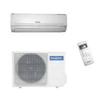
Do you have a question about the Panasonic CU-PW12DKE and is the answer not in the manual?

Panasonic CU-PW12DKE Specifications

General IconGeneral
RefrigerantR32
Indoor Unit Dimensions (W x H x D)779 x 290 x 209 mm
Outdoor Unit Dimensions (W x H x D)650 x 511 x 230 mm
Cooling Capacity3.5 kW
Energy Efficiency Ratio (Cooling)3.5
Energy Efficiency Ratio (Heating)4.0
Power Supply220-240 V, 50 Hz

Summary

1 Features

2 Functions

Remote Control

Details on using the remote control for various air conditioner functions.

3 Product Specifications

4 Dimensions

Indoor Unit

Provides detailed measurements and diagrams for the indoor unit.

Outdoor Unit

Provides detailed measurements and diagrams for the outdoor unit.

5 Refrigeration Cycle Diagram

6 Block Diagram

7 Wiring Diagram

8 Operation Details

8.1 Cooling Mode Operation

Explains the operation sequence and controls for cooling mode.

8.2 Soft Dry Mode Operation

Details the operation and characteristics of the soft dry mode.

8.3 Heating Mode Operation

Outlines the operational procedures and controls for heating mode.

Deice Control

Describes the process and conditions for de-icing the outdoor unit.

8.4 Automatic Mode Operation

Explains how the unit determines and operates in automatic mode.

8.5 Air Quality Sensor Control

Details the functionality and control of the air quality sensor.

8.6 Demo Mode & Ventilator Control

Instructions for demo mode and controlling an optional ventilator based on air quality.

8.8 Cursor Key Function & Fan Motor Control

Explains remote cursor key function and indoor fan motor control.

8.10 Auto Restart & Airflow Direction Control

Covers auto restart function and airflow direction control methods.

9 Installation Instructions

9.1. Safety Precautions

Important safety warnings and precautions to follow before installation.

Installation Diagrams and Location Selection

Guidelines for unit placement, diagrams, and choosing optimal installation locations.

9.2. INDOOR UNIT Installation

Instructions and procedures for installing the indoor unit.

9.3. OUTDOOR UNIT Installation

Instructions and procedures for installing the outdoor unit.

9.3.4. Evacuation & Air Purging

Procedures for system evacuation and air purging for R410A.

9.3.6. Cable Connection & Pipe Insulation

Guidance on connecting cables and insulating piping for proper installation.

Installation Completion Checks

Covers drain water disposal, drainage verification, performance evaluation, and final checks.

10 Installation and Serving Air Conditioner Using R410A

10.1. R410A Refrigerant Outline & Safety

Provides an overview of R410A refrigerant, its characteristics, and safety measures.

10.2. Tools for R410A Installation & Servicing

Lists necessary ordinary and R410A specific tools for installation and servicing.

10.3. Refrigerant Piping Work

Procedures and precautions for performing refrigerant piping work.

10.4. Installation, Transferring, Servicing Procedures

Guides on installation, unit transfer, and servicing procedures, including brazing.

11 Disassembly of the parts

Removal Procedure For Intake Grille

Instructions for safely removing the intake grille from the unit.

Removal Procedure For Front Grille

Steps to remove the front grille, including cap and screw removal.

Removal Procedure For Electronic Controller

Detailed steps for removing the electronic controller and its components.

Removal Procedure For the Discharge Grille

Instructions for separating the drain hose and removing the discharge grille.

Removal Procedure For Cross Flow Fan

Guides on disassembling the fixing board and removing the cross flow fan and motor.

Remote Control Reset

Procedure to reset the remote control if the display is chaotic.

12 Troubleshooting Guide

12.1. Refrigeration Cycle System

Diagnosing malfunctions by checking the refrigeration cycle and standard values.

12.2. Pressure and Electric Current Relationships

Explains how pressure and current relate to different operating conditions.

12.3. Compressor Malfunction Diagnosis

Methods for diagnosing compressor malfunctions based on symptoms.

13 Technical Data

Thermostat Characteristics

Graphs showing thermostat behavior across different modes and temperatures.

Operation Characteristics

CS/CU-PW9DKE Operation and Piping Length Characteristics

Details cooling, heating, and piping length performance for CS/CU-PW9DKE.

CS/CU-PW12DKE Operation and Piping Length Characteristics

Details cooling, heating, and piping length performance for CS/CU-PW12DKE.

14 Exploded View

15 Replacement Parts List

16 Exploded View

17 Replacement Parts List

18 Electronic Diagram

18.2 Remote Controller

Related product manuals