7
EN
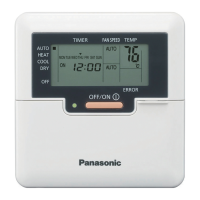
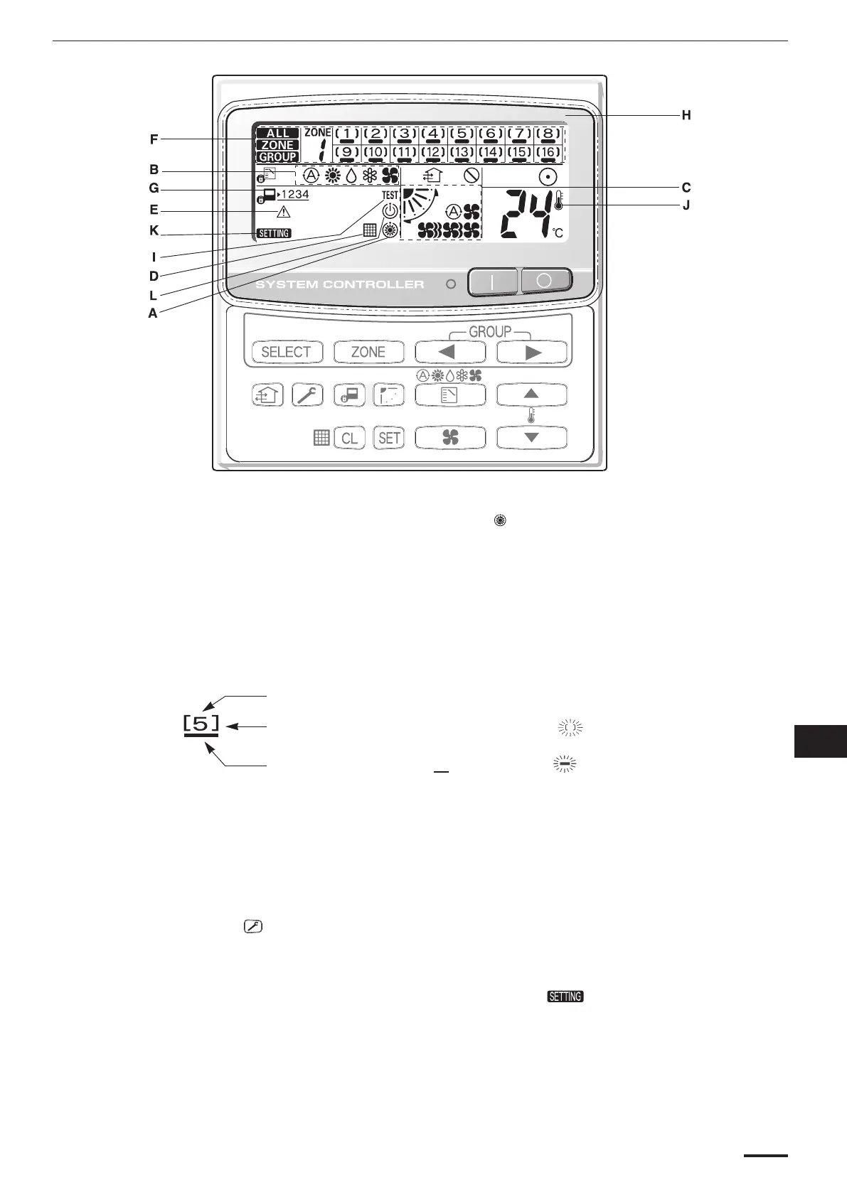
Display
Description
A: When the unit is in the heating standby mode, the indicator appears.
B: The currently selected operation mode is displayed.
C: The currently selected FAN SPEED, Airfl ow Direction and SWEEP settings are displayed.
D: This indication appears when the fi lter needs cleaning.
E: This indication appears only when an abnormality occurs within a unit.
F: The currently selected mode (ALL, ZONE or GROUP), ZONE number and GROUP number are
displayed.
GROUP number display (no fi gure: no number registered)
GROUP state display ( [ ] registered group, currently selected group)
Operation state display ( on, no sign: off, alarm)
G: The currently selected central control mode (1, 2, 3 or 4) is displayed.
H: Lights when any of the air conditioners under the system control is operating; turns off when
none of the air conditioners under the system control is operating. Blinks when any conditioner is
operating under abnormal conditions and its protection functionality is working.
I: When the button is pressed for more than four seconds, the TEST indicator appears.
J: This indication appears when the temperature is set.
K: When turning on the power switch of the system controller. sign blinks for a few minutes.
While blinking, any controls using the system controller are inhibited. This is because the system
controller is verifying connected groups.
L: Appears during the peak cut mode (Demand) if an electric heat pump (EHP) air conditioner is
used or during standby if a gas heat pump (GHP) air conditioner is used.
CZ-64ESMC2all.indb7CZ-64ESMC2all.indb7 2011/09/0714:37:492011/09/0714:37:49
 Loading...