EasyManua.ls Logo

Panasonic DC-S1P User Manual

Panasonic DC-S1P
66 pages
To Next Page IconTo Next Page
Page #1 background imageLoading...
Page #1 background image
© Panasonic Corporation 2019 Unauthorized copy-
ing and distribution is a violation of law.
ORDER NO. DSC1903002CE
B26
Digital Camera/Body/Lens Kit
Model No. DC-S1P
DC-S1PP
DC-S1E
DC-S1EE
DC-S1GA
DC-S1GC
DC-S1GD
DC-S1GH
DC-S1GK
DC-S1GN
DC-S1GT
DC-S1MP
DC-S1MPP
DC-S1ME
DC-S1MEE
DC-S1MGA
DC-S1MGC
DC-S1MGD
DC-S1MGH
DC-S1MGK
DC-S1MGN
DC-S1MGT
Question and Answer IconNeed help?

Do you have a question about the Panasonic DC-S1P and is the answer not in the manual?

Panasonic DC-S1P Specifications

General IconGeneral
Camera TypeMirrorless
Sensor TypeCMOS
Megapixels24.2MP
ISO Range100-51200 (expandable to 50-204800)
Viewfinder TypeElectronic
Touch ScreenYes
ConnectivityWi-Fi, Bluetooth
BatteryDMW-BLJ31
Effective Pixels24.2 MP
Sensor Size35.6 mm x 23.8 mm
Lens MountLeica L
Shutter Speed1/8000 sec to 60 sec
Continuous Shooting9 fps
Video Resolution4K/60p
Viewfinder Resolution5.76 million dots
LCD Screen3.2-inch Free-Angle Touch LCD
Battery LifeApproximately 380 shots
Weight (body only)898 g
Dimensions148.9 x 110 x 96.7 mm
Image Stabilization5-axis sensor-shift image stabilization

Summary

Safety Precautions

General Guidelines

General safety notices, component replacement, isolation transformer use, lead dress, protective devices, and leakage current checks.

Leakage Current Cold Check

Procedure to measure resistance between plug and metallic parts for safety.

Leakage Current Hot Check

Procedure to measure voltage across a resistor connected between exposed parts and ground.

Warning

Prevention of Electrostatic Discharge (ESD) to Electrostatically Sensitive (ES) Devices

Techniques to prevent damage to sensitive electronic components from static electricity during servicing.

How to Recycle the Lithium Ion Battery

Information on how to recycle lithium-ion batteries, including contact information.

How to Replace the Lithium Battery

Replacement Procedure

Detailed steps for removing, desoldering, and replacing the lithium battery.

Caution for AC Cord

Information for Your Safety

Safety warnings regarding rain, moisture, accessories, and not removing covers.

Caution for AC Mains Lead

Safety information about the 3-pin plug, fuse replacement, and wiring.

Important

Wire color coding for connecting the mains lead to the plug terminals.

Before Use

Instructions for removing the connector cover before using the appliance.

How to Replace the Fuse

Step-by-step guide for replacing the fuse in the mains plug.

Service Navigation

Introduction

Explains the manual's purpose for service personnel and ordering parts.

About service of bundled lenses

Directs users to a separate service manual for bundled lenses.

Important Notice

Recommends using a clean box and provides critical notices for specific parts.

Camera Body Unit

Details on servicing the camera body, including serial number rewriting and grip rubber replacement.

About Main P.C.B. (Addition of the operation of rewriting Serial number)

Procedure for backing up and rewriting serial numbers after Main P.C.B. or Flash-ROM replacement.

About prohibition of reusing Grip Rubber

Advises against reusing grip rubbers due to weakened adhesive and recommends using new ones.

About Simplicity flange back adjustment

About Shutter Mount Base Unit

About Firmware Update

About Flexible Cable and Connector

Service Notes

About Wi-Fi/Bluetooth Function

Explains Wi-Fi/Bluetooth functions for remote operation and image transfer, including smartphone app usage.

Important Notice of Servicing

Instructions on erasing customer personal information and providing documents to the customer after service.

General Description About Lead Free Solder (PbF)

Service caution for repair work using Lead Free Solder (PbF)

How to Define the Model Suffix (NTSC or PAL Model)

Defining Methods

Details on how to define the model suffix by checking the nameplate on the unit.

Initial Settings

Display the Initial Settings

Cancel "Strict" mode

Choose the Model Suffix in "Initial Settings"

Set the Model Suffix in "Initial Settings"

Confirmation

Specifications

Camera Body

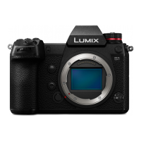
Specifications for the DC-S1 camera body, including power, recording media, lens mount, and sensor details.

Recording format for still images

File format for 6K/4K photos

Picture size (pixels)

Image quality for pictures

Recording format for video

Image quality for videos

Viewfinder / Monitor

Focus

Exposure control

Image stabiliser

White balance

Shutter

Burst recording

Minimum illumination

Flash (when using an external flash)

Zoom

Microphone / Speaker

Interface

Dimensions / Mass

Operating environment

Wi-Fi

Bluetooth

Battery charger (Panasonic DMW-BTC14):

AC adaptor (Panasonic DVLV1001Y):

Battery pack (lithium-ion) (Panasonic DMW-BLJ31):

Location of Controls and Components

Camera Body

Identifies and describes the location of various controls and buttons on the camera body.

Dioptre adjustment dial

Operation lock lever

(Playback) button

Monitor lock lever

Monitor/Touch screen

Video rec. button

(AF mode) button

[AF ON] button

Focus mode lever

Joystick

Fn buttons

Specific Fn button assignments (Centre)

Specific Fn button assignments (Top/Left/Bottom/Right)

[Q] button

Cursor buttons

Control dial

[MENU/SET] button

[3] (Cancel) button

[血] (Delete) button

[DISP.] button

Button lighting feature

Eye sensor

Viewfinder

Eye cup

Eye cup lock lever

Tripod mount

Battery grip connector

Card slot 2

Card slot 1

Card door lock lever

Card door

Card access lamp

DC Coupler cover

Battery door

Battery door release lever

Shoulder strap eyelet

Self-timer lamp / AF assist lamp

Fn button (Fn1)

Grip

Preview button / Fn button (Fn2)

Lens release button

Flash synchro socket

[REMOTE] socket

Headphone socket

USB port

[HDMI] socket

Fn lever

Mount

Contact points

Sensor

Lens lock pin

Lens fitting mark

Service Mode

Error Code Memory Function

Explains the error code memory function, how to display error codes, and provides an example display.

Error Code List

Error Code List

Error Code List

Troubleshooting Guide

Checking Method of Body and Interchangeable Lens

Provides a quick reference for the mode dial settings and how to access the basic menu.

Basic Menu

[PLAYBACK]

Other than Basic Menu

[C3 Custom Mode]

Wi-Fi Circuit (WIFI BT P.C.B.)

How to Remove Wi-Fi Password Protection

Steps to reset network settings to remove Wi-Fi password protection and check operation.

Checking of trouble caused by Wi-Fi Circuit or not

Procedure to confirm Wi-Fi circuit functionality by checking for the wireless access point name (SSID) display.

Service Fixture & Tools

Service Fixture and Tools

Lists and illustrates various service fixtures and tools required for camera maintenance and adjustment.

CC Filter (CC-G2.5)

CC Filter (CC-Y10)

CC Filter (CC-Y2.5)

Gray Card

Torque Driver

Hex Driver

Lens Cleaning Kit (BK)

Clean Box

When Replacing the Main P.C.B.

Service Position

Disassembly and Assembly Instructions

Disassembly Flow Chart

Provides a visual flow chart for disassembling the camera unit and indicates assembly is the reverse.

P.C.B. Location

Disassembly Procedure

Precautions when disassembling / assembling

Removal of the Rear Case 1 Unit

NOTE: (When Replacing) - Front Grip (L)

NOTE: (When Replacing) - Front Grip (R)

NOTE: (When Replacing) - Rear Grip

NOTE: (When Installing) - Rear Grip

NOTE: (When Assembling the Front Grip (R))

NOTE: (When Installing) - Fibers and Dust

NOTE: (When Assembling the Rear Grip)

NOTE: (When Installing) - Front Grip (R)

NOTE: (When Assembling the Front Grip (L))

NOTE: (When Installing) - Front Grip (L)

Removal of the Top 1 Unit

NOTE: (When Replacing) - Flex Handling

NOTE: (When Installing) - Fibers and Dust

Removal of the Main P.C.B.

NOTE: (When Replacing) - Pad and Gasket

NOTE: (When Replacing) - Flex Handling

Removal of the EXT MIC HP P.C.B.

Removal of the Main Frame

Removal of the Tripod

Removal of the Shutter Mount Base Unit & Image Sensor Unit

IMPORTANT NOTICE: - Shaded Portion Handling

Removal of the Battery Case Unit

NOTE: (When Installing) - Fibers and Dust

Removal of the WIFI BT P.C.B.

NOTE: (When Replacing) - WP Poron

NOTE: (When Installing) - WP Poron

Removal of the Battery FPC Plate, Battery FPC Unit

NOTE: (When Replacing) - Double-sided Tape

Removal of the Shutter Spacer Unit, Front Dial Unit

Replacing of the Button Battery

Removal of the SD Door Unit

Removal of the Rear Plate Unit

NOTE: (When Replacing) - Flex Handling

Removal of the LVF Unit

Removal of the Rear IF P.C.B.

NOTE: (When Replacing) - Flex Handling

Removal of the LCD Unit

NOTE: (When Replacing) - Flex Handling

Removal of the Rear Operation FPC Unit

Removal of the Rear Case Unit

NOTE: (When Installing) - Fibers and Dust

Removal of the Hinge Unit

NOTE: (When Replacing) - Flex Handling

IMPORTANT NOTICE: - Simplicity Flange Back Adjustment

Removal of the Image Sensor Unit

NOTE: (After Assembling) - Post-Assembly Checks

Removal of the Shutter Mount Base Unit

Measurements and Adjustments

Matrix Chart for Replaced Part and Necessary Adjustment

A matrix showing which adjustments are necessary after replacing specific parts like Main P.C.B., Image Sensor Unit, etc.

NOTE: (About Simplicity flange back adjustment)

Abstract of "Simplicity flange back adjustment"

NOTE: (When exchange the Shutter Mount Base Unit)

NOTE: (When exchange the Main P.C.B. and/or Flash-ROM (IP2201))

Maintenance

Notice in External Cleaning

Provides instructions for cleaning the camera body, image sensor, and LVF unit.

About the Body

Steps for cleaning the outer casing of the camera body using a brush and cloth.

Dust/Dirt on the Outer Casing Part (S)

Instructions for blowing off dust and wiping the outer casing with a soft cloth.

Dust/Dirt on the Image Sensor

Procedure for cleaning the image sensor using a blower and lens cleaning kit.

About the LVF Unit

Steps for disassembling and cleaning the LVF unit's lens.

Block Diagram

Overall Block Diagram

Presents a comprehensive block diagram illustrating the interconnections of major internal components and modules.

Wiring Connection Diagram

Interconnection Diagram

Shows the detailed wiring connections between various PCBs, units, and connectors within the camera.

Schematic Diagram

Printed Circuit Board

Exploded View and Replacement Parts List

Related product manuals