7
RQT7392
Getting started
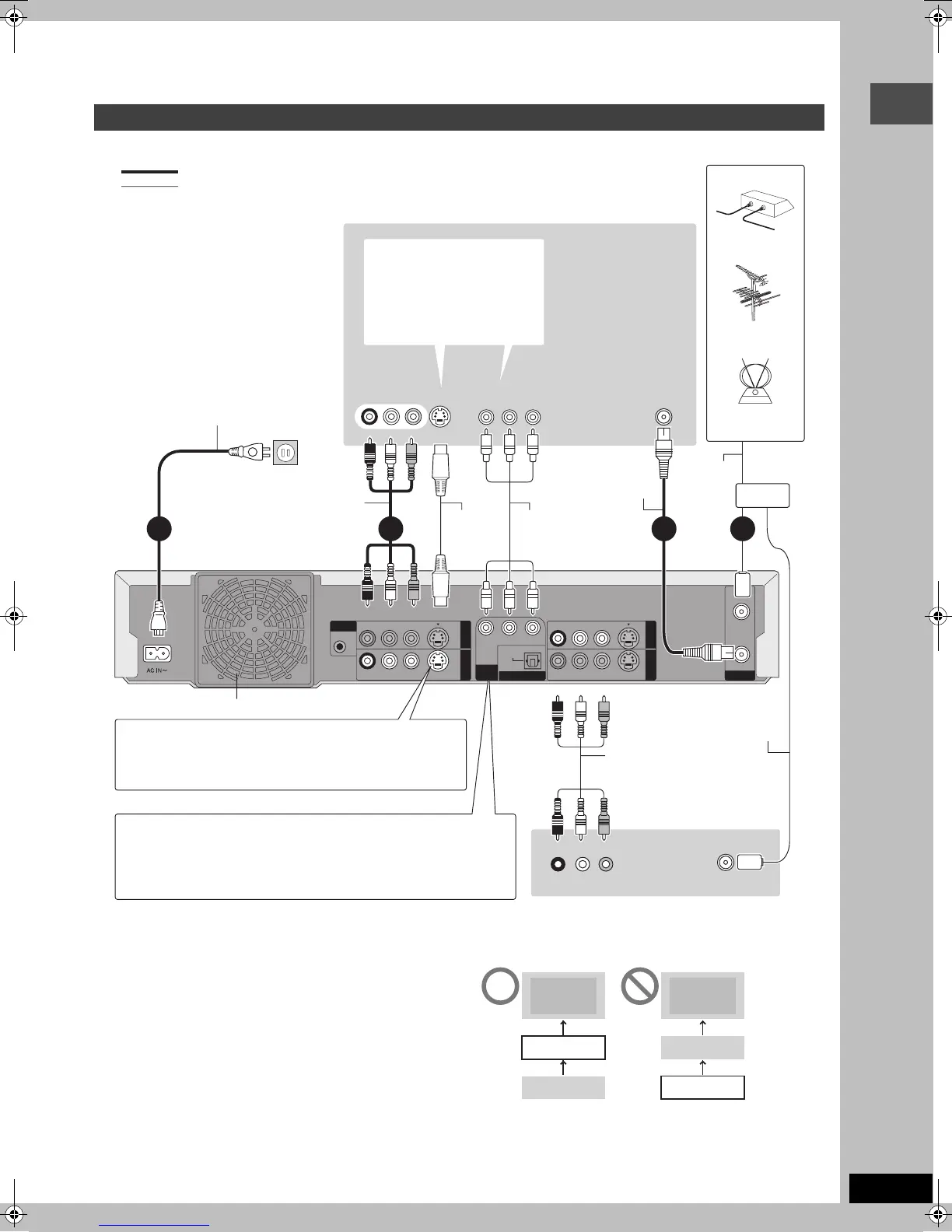
≥The equipment connections described are examples.
≥Before connection, turn off all equipment and read the appropriate operating instructions.
≥Peripheral equipment and optional cables sold separately unless otherwise indicated.
A to X are indexes for Spanish Quick Reference.
∫ 75 ≠ coaxial cable
The picture and sound signal from this unit does not go through the
75 ≠ coaxial cable to the television. Make sure you connect one of
the following terminals on this unit to the television: the AUDIO/
VIDEO OUT terminal, the S-VIDEO OUT terminal or the
COMPONENT VIDEO OUT terminal. If the television has none of
these terminals, consult your local dealer.
≥Refer to page 9 if the antenna connector doesn’t match.
Do not connect the unit through a video cassette recorder
Video signals fed through video cassette recorders will be affected
by copyright protection systems and the picture will not be shown
correctly on the television.
≥When connecting to a television with a built in VCR, connect to
the input terminals on the television side, not the VCR side.
Connecting a television and VCR
YPB PR
R - AUDIO - L
VIDEO
S-VIDEO
R - AUDIO - L
VIDEO
S-VIDEO
OPTICAL
G-LINK
(L1)
(L3)
COMPONENT
VIDEO OUT
(480P/480I)
DIGITAL AUDIO OUT
(PCM/BITSTREAM)
IN1
IN3
R - AUDIO - L
VIDEO
S-VIDEO
R - AUDIO - L
VIDEO
S-VIDEO
OUT1 OUT2
VHF/UHF
RF IN
RF OUT
VHF/UHF
RF IN
VIDEO
OUT
VHF/UHF
RF IN
R L
AUDIO OUT
COMPONENT
VIDEO IN
AUDIO IN
R L
S VIDEO IN
VIDEO IN
3214
L To the
antenna
E Outdoor
antenna
D Cable TV
F Indoor
antenna
B Television
M Audio/Video
cable
K Antenna
cable
I To household AC outlet
(AC 120 V, 60 Hz)
X Video cassette recorder
R Cooling fan
O Component
video cable
Connecting a cable TV box
➡ page 8
G AC power supply cord
Connect only after all other
connections are complete.
T This unit
J 75 ≠ coaxial
cable
M Audio/Video
cable
P Splitter
indicates included accessories.
indicates accessories not included.
1 – 4 are required connections. Connect in the numbered order.
S To IN1 (L1)
C When making this
connection, ensure you
connect the audio cables to
the corresponding audio
input terminals on the
television.
H
Red White Yellow
U S-VIDEO OUT terminal
The S-VIDEO OUT terminal achieves a more vivid picture
than the VIDEO OUT terminal. (Actual results depend on the
television.)
W
COMPONENT VIDEO OUT terminal
These terminals can be used for either interlace or progressive output
(➡ page 53) and provide a purer picture than the S-VIDEO OUT
terminal.
≥Connect to terminals of the same color.
N S-Video
cable
H
Red White Yellow
H
Red White Yellow
H
Red White Yellow
V Use a splitter if you also
want to connect the
antenna to your VCR.
Q To OUT1 or OUT2
J 75 ≠ coaxial cable
➡ below
A
B Television B Television
T This unit
X VCR
X VCR
T This unit
7392en.book 7 ページ 2004年4月27日 火曜日 午後5時30分