Do you have a question about the Panasonic DMR-ES30VP and is the answer not in the manual?
General guidelines for servicing and safety precautions.
Cautionary notes and procedures for replacing fuses safely.
Information and distinction of lead-free solder (PbF) used in PCBs.
Explanation of the Quick Start (REC) principle and its operation.
Procedure for forcibly ejecting a DVD from the RAM-Drive unit.
Steps to take when the forcible disc eject method fails.
Method for compulsory unloading of a VHS cassette tape.
Manual removal of VHS cassette by rotating the loading motor.
Manual removal of VHS cassette tape after disassembling the mechanism.
Steps to execute the Service Mode for DVD diagnostics.
Explains the Self-Diagnosis functions and error codes for DVD.
Details on setting and using special modes for DVD operations.
Explanation of VHS self-diagnosis functions and error code display.
Instructions for setting special modes in the VHS section.
Procedure for entering and using VHS service modes.
Conditions and rules for memorizing VHS self-diagnosis history.
Details on VHS error numbers and associated supplementary data.
A flowchart illustrating the procedure for disassembling the unit.
List of service fixtures and tools required for DVD section repair.
List of service fixtures and tools required for VHS section repair.
Procedure for checking and repairing the Power P.C.B.
Steps for checking and repairing the Digital I/F P.C.B.
Procedure for checking and repairing the Main P.C.B.
Steps for checking and repairing the Digital P.C.B.
Procedures for checking and servicing the DVD-RAM Drive.
Cautionary measures after replacing the RAM Drive.
Steps to take when the unit fails after replacing Timer Microprocessor or Main P.C.B.
Adjustment procedures for VHS after replacing key components.
Procedure for adjusting X-Value and Linearity on VHS P2 and P3 Posts.
Precautions and initialization steps after replacing the VHS Microprocessor.
Voltage and waveform data for the Power P.C.B.
Voltage and waveform data for the Digital I/F P.C.B.
Voltage and waveform data for the Main P.C.B.
Voltage and waveform data for the FL Drive P.C.B.
Voltage data for the Front Jack P.C.B.
Voltage data for the P9001 Connector.
Visual representations of various circuit waveforms for reference.
List of abbreviations used for DVD functions and components.
List of abbreviations used for VHS functions and components.
Block diagram illustrating the power supply system of the unit.
Block diagram of the digital I/F regulator circuits.
Block diagram showing the digital I/F timer circuitry.
Block diagram of the system control and servo mechanisms.
Block diagram illustrating the audio signal processing path.
Block diagram illustrating the video signal processing path.
Schematic showing the interconnection between various PCBs and components.
Detailed schematic of the main power supply circuit.
Schematic of the sub-power section of the Digital I/F P.C.B.
Schematic of the digital I/F section of the Digital I/F P.C.B.
Schematic of the DVD output section of the Digital I/F P.C.B.
Schematic of the I/O Tuner section on the Main P.C.B.
Schematic of the Syscon/Servo/Timer section on the Main P.C.B.
Schematic of the Video section on the Main P.C.B.
Schematic of the VHS Audio section on the Main P.C.B.
Schematic diagram of the FL Drive circuitry.
Schematic diagram of the Front Jack connections.
Layout of components and traces on the Power P.C.B.
Layout and address information for components on the Digital I/F P.C.B.
Component layout for all sections of the Main P.C.B.
Layout of components on the Front Jack P.C.B.
Layout of components on the FL Drive P.C.B.
Exploded view of casing parts and mechanism components (Section 1).
Exploded view of casing parts and mechanism components (Section 2).
Exploded view of the VHS mechanism components.
Exploded view of the product packaging and included accessories.
| Recording Formats | DVD-RAM, DVD-R, DVD-RW |
|---|---|
| Video Format | NTSC |
| Video Output | Composite, S-Video, Component |
| Tuner | NTSC |
| VCR | Yes |
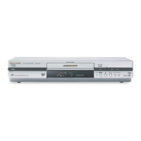
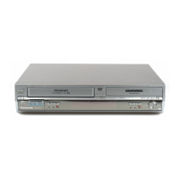
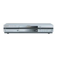
| Type | DVD Recorder |
| Playback Formats | DVD-Video, DVD-R, CD, CD-R/RW |
| Audio Output | Digital Optical |