Do you have a question about the Panasonic DMR-EH80VEG and is the answer not in the manual?
General guidelines for safe servicing procedures, including handling of sharp edges and protective devices.
Procedure for checking leakage current with the unit unplugged by measuring resistance.
Procedure for checking leakage current with the unit plugged in, using a resistor and capacitor.
Techniques to prevent damage to sensitive electronic components from static electricity.
Safety precautions regarding the laser diode, including avoiding disassembly and direct viewing.
Guidance on using lead-free solder and appropriate soldering iron temperatures.
Methods for grounding work areas and human bodies to prevent ESD damage.
Specific handling instructions for the optical pick-up unit to prevent ESD damage.
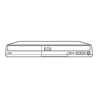
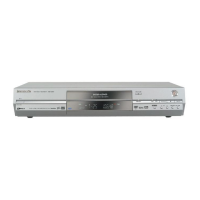
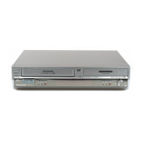
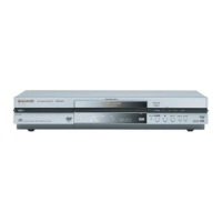
Description of the unit's controls on the front panel and remote commander.
Explanation of the quick start recording function principle and operation.
Procedures for forcibly ejecting a DVD disc when normal ejection fails.
Steps to follow when the forcible disc eject function cannot be completed.
Method for removing a VHS cassette tape via compulsory unloading.
Procedure for manual removal of a VHS cassette tape.
Steps for manually removing a VHS cassette tape after removing the mechanism.
Information on error codes and their meanings displayed during self-diagnosis.
Instructions for entering and setting various special modes for DVD functions.
Details on accessing and operating different service modes for DVD functions.
Procedures for setting special modes related to VHS functions.
Guidance on accessing and utilizing service modes for VHS operations.
Explanation of VHS self-diagnosis features and error code memorization.
A step-by-step chart illustrating the disassembly sequence of the unit.
Diagram showing the location of various Printed Circuit Boards within the unit.
Important safety note regarding cassette tape insertion during disassembly.
Instructions for removing the top case of the unit.
Steps involved in removing the front panel assembly.
Instructions for removing the front jack and FL drive PCBs.
Steps to remove the power supply printed circuit board.
Procedure for removing the rear panel and fan motor unit.
Instructions for removing the VCR mechanism unit.
Important notes for correctly attaching the VCR mechanism unit.
Steps for removing the main printed circuit board.
Procedure for removing the tuner, converter, and decoder modules.
Instructions for removing the DVD-RAM drive unit.
Information and cautions for replacing the digital PCB, including HDD formatting.
Procedure for replacing the hard disc drive, including HDD formatting.
Instructions for removing the SD card PCB.
Steps for removing the digital interface PCB.
Detailed steps for accessing and repairing the power supply PCB.
Procedure for checking and repairing the digital interface PCB.
Steps for accessing and repairing the main PCB.
Procedure for checking and repairing the DVD-RAM drive.
Steps for checking and repairing the hard disc drive.
Procedure for checking and repairing the SD card PCB.
Notes on confirming RAM drive operation after replacement.
Procedure to reset the timer microprocessor after replacement.
Procedure for adjusting PG shifter after EEPROM replacement.
Steps for PG Shifter Automatic Adjustment after part replacement.
Procedure for adjusting X-Value and Linearity for VHS playback.
Procedure to reset IC6001 after VHS microprocessor replacement.
Checklist for verifying normal operation after making repairs.
Illustrations of various waveforms measured with a PAL colour bar signal.
List of abbreviations used in the DVD section of the manual.
List of abbreviations used in the VHS section of the manual.
Block diagram illustrating the power supply circuit.
Block diagram showing the digital interface regulator circuits.
Block diagram of the system control, servo, and timer functions.
Block diagram illustrating the audio signal path.
Block diagram showing the video signal processing path.
Block diagram for the digital interface PCB.
Detailed schematic diagram of the power supply circuit.
Schematic diagram detailing the DVD output circuitry.
Schematic diagram illustrating the unit's interface connections.
Schematic diagram for the Input/Output and Tuner sections.
Schematic diagram for the system control, servo, and timer main board.
Schematic diagram of the VHS audio processing circuitry.
Schematic diagram for the video processing circuitry.
Schematic diagram for the NICAM decoder circuit.
Schematic diagram for the front panel jack connections.
Schematic diagram for the FL drive board.
Schematic diagram for the SD card and DV input interfaces.
Component layout diagram for the power PCB (component side).
Component layout diagram for the power PCB (solder side).
Component layout diagram for the main PCB (component side).
Component layout diagram for the main PCB (solder side).
Component layout diagram for the digital I/F PCB (component side).
Component layout diagram for the digital I/F PCB (solder side).
Layout diagrams for the NICAM decoder PCBs (VEP07A51A / VEP07A51B).
Layout diagram for the NICAM decoder PCB (VEP07A51F).
Layout diagrams for the front jack PCB (component and solder sides).
Layout diagrams for the FL drive PCB (component and solder sides).
Layout diagrams for the SD card PCB (component and solder sides).
Exploded view illustrating mechanism and casing components.
Exploded view showing front panel components.
Exploded view illustrating VHS mechanism parts.
Diagram showing packing contents and accessories.
List of replacement parts for the VHS mechanism.
List of replacement parts for the mechanism and casing.
List of PCBs included within the main PCB assembly.
List of replacement parts for packing and accessories.
Comprehensive list of electrical components used in the unit.
List of specialized tools and fixtures required for service.
Block diagram formatted for A4 size printing.
Schematic diagram formatted for A4 size printing.
Schematic diagram of the power PCB formatted for A4 size printing.
Schematic diagram of the main PCB (component side) for A4 printing.