Do you have a question about the Panasonic DMR-E75VP and is the answer not in the manual?
Provides essential rules for safe operation and maintenance.
Procedure to check for electrical leakage with the unit unplugged.
Procedure to check for electrical leakage with the unit powered on.
Information on lead-free solder and its properties.
Steps for ejecting a disc when the normal method fails.
Procedures for removing a disc when normal and forcible eject fail.
Steps for removing a VHS cassette tape using service mode.
Method for removing VHS cassette tape by manually operating the loading motor.
Procedure for removing VHS cassette tape after the mechanism is disassembled.
Provides error information for service personnel.
Details various special modes for settings and diagnostics.
Describes various service modes accessible for maintenance.
Explains error codes displayed on the VHS side.
Details various special modes for VHS section settings.
Describes service modes available for VHS operations.
Overview of service modes and their displayed data.
Explains how self-diagnosis history is stored.
Explains how self-diagnosis history is stored.
Details how to erase self-diagnosis history data.
How to display self-diagnosis history and supplementary data.
How to view supplementary data 3 and 4 during history display.
Explains how self-diagnosis memory stores error data.
Explains the memorization of error numbers and supplementary data.
Visual guide for disassembling the unit's casing and internal parts.
Identifies the locations of various Printed Circuit Boards (PCBs) within the unit.
Important cautionary notes regarding cassette tape handling during disassembly.
Steps for removing the top case of the unit.
Steps for removing the front panel of the unit.
Procedure for removing front jack and FL drive PCBs.
Steps for removing the rear panel and fan motor.
Procedure for disconnecting and removing the I/O PCB.
Steps for disconnecting and removing the VTR mechanism unit.
Precautions for correctly attaching the VTR mechanism unit.
Procedure for disconnecting connectors and removing the main PCB.
Steps for removing the DVD-RAM drive.
Procedure for removing the digital PCB.
Steps for removing the power and digital I/F PCB.
Guidance for checking and repairing the power and digital I/F PCB.
Steps for checking and repairing the main PCB.
Guidance for checking and repairing the digital PCB.
Steps for checking and repairing the I/O PCB.
Procedure for checking and repairing the DVD-RAM drive.
Precautions after replacing the RAM drive.
Troubleshooting steps when the unit is abnormal after replacing the timer microprocessor.
Adjustment procedures required after replacing key internal components.
Adjustment procedures for X-Value and Linearity (P2/P3 Posts).
List of abbreviations related to DVD functions.
List of abbreviations related to VHS functions.
Illustrates the power supply architecture of the unit.
Diagram showing the digital interface regulator circuitry.
Block diagram of the digital interface timer.
Diagram of the system control, servo, and timer functions.
Block diagram illustrating the audio processing path.
Block diagram of the video signal processing.
Overall block diagram of the digital circuitry.
Pinout details for digital ICs.
Overall schematic showing interconnections between major units.
Exploded view of casing and mechanism parts, section 1.
Exploded view of casing and mechanism parts, section 2.
Exploded view of the VHS mechanism.
Exploded view of packing and accessories.
| Video Recording System | MPEG-2 |
|---|---|
| Connectors Front | S-Video input, Composite video input, Stereo audio input |
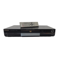
| Remote Control | Yes |
| Tuner | NTSC |
| Video Input | Composite, S-Video |
| Weight | 11.9 lbs |
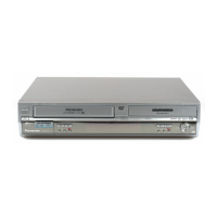
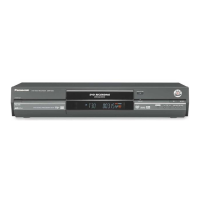
| Type | DVD Recorder with VCR |
| Recording Formats | DVD-RAM, DVD-R, DVD-RW |
| Playback Formats | DVD-Video, DVD-RAM, DVD-R, DVD-RW, CD, CD-R, CD-RW |
| Audio Recording System | Dolby Digital |
| Connectors Rear | S-Video Output, Composite Video Output, Component Video Output, Stereo Audio Output, RF Input, RF Output |
| Video Output | S-Video, Composite, Component |