39
9.3. Disassembly Procedures
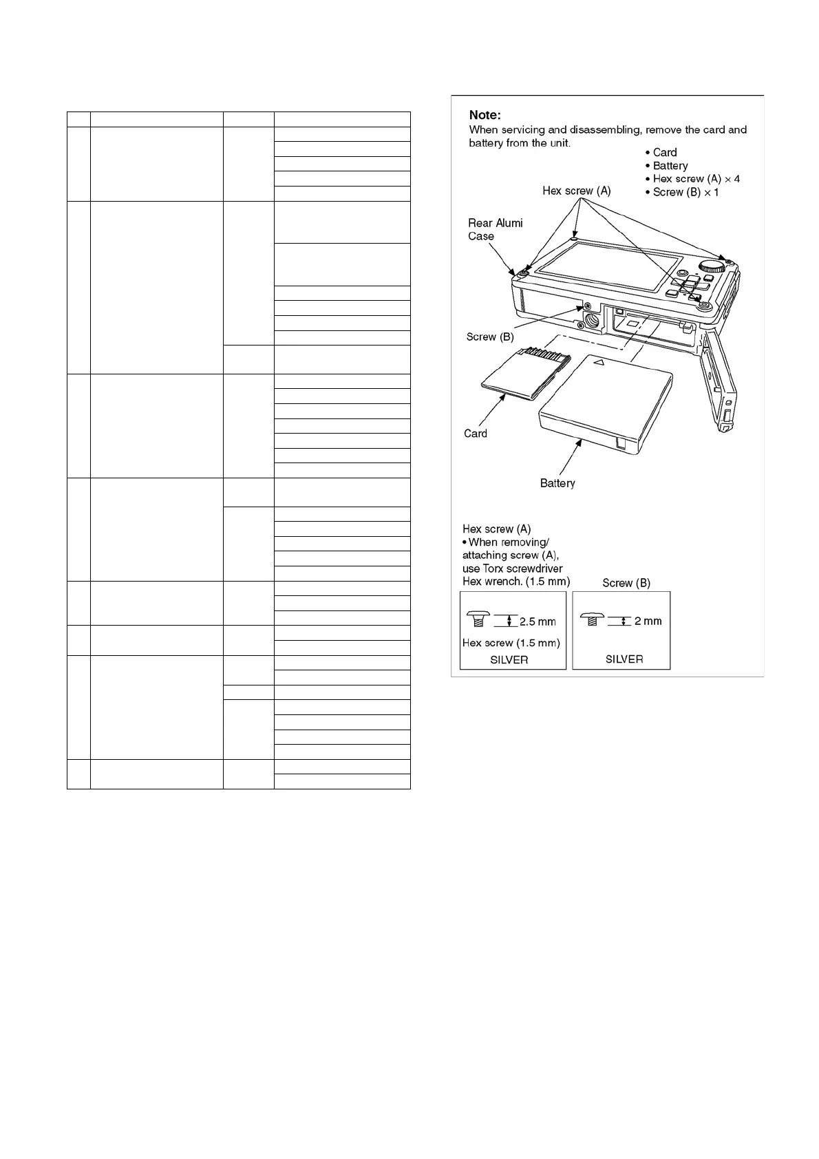
9.3.1. Removal of Rear Alumi Case
Fig. D1
No. Item Fig. Removal
1 Rear Alumi Case Fig. D1 Card
Battery
4 Hex Screws (A)
1 Screw (B)
Rear Alumi Case
2 Rear Case Unit Fig. D2 4 Screws (C)
(Tightening torque is
regretted)
2 Screws (D)
(Tightening torque is
regretted)
FP9004 (Flex)
FP9005 (Flex)
FP9007 (Flex)
Rear Case Unit
Fig. D3 Note when attaching Rear
Case Unit
3 Camera Lens Unit Fig. D4 Peel off Sheet
4 Screws (E)
1 Screw (F)
FP9002 (Flex)
FP9003 (Flex)
Lens Plate
Camera Lens Unit
4 Main P.C.B. Fig. D5 Note before removal of
Main P.C.B.
Fig. D6 1 Screw (G)
1 Screw (H)
FP9001 (Flex)
FP9006 (Flex)
Main P.C.B.
5 Battery Case Unit Fig.D7 2 Screws (I)
1 Screw (J)
Battery Case Unit
6 Flash P.C.B. Fig. D8 1 Screw (K)
Flash P.C.B.
7 Rear Operation P.C.B.,
Mode Dial (1)
Fig. D9 9 Screws (L)
Rear FPC Plate
Fig. D10 Rear Operation P.C.B.
Fig. D11 1 Screw (M)
Mode Dial Piece
Mode Dial O-ring
Mode Dial (1)
8 LCD Unit Fig. D12 4 Screws (N)
LCD Unit