43
9.1.3. Disassembly Procedure
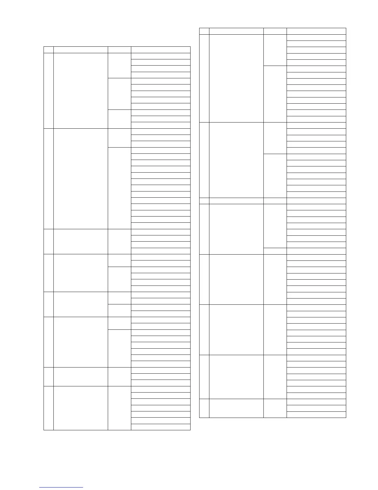
No. Item Fig Removal
1 Rear Case Unit (Fig. D1) Card
Battery
2 Screws (A)
5 Screws (B)
(Fig. D2) EYE CUP Unit
2 Screws (C)
2 Screws (D)
1 Screw (E)
LVF DPT Knob
(Fig. D3) FP9010 (Flex)
FP9300 (Flex)
Rear Case Unit
2 Main P.C.B. (Fig. D4) 2 Screws (F)
Battery Contact Cover Unit
Water Label
(Fig. D5) FP9001 (Flex)
FP9002 (Flex)
FP9003 (Flex)
FP9004 (Flex)
FP9005 (Flex)
FP9007 (Flex)
FP9009 (Flex)
FP9302 (Flex)
P9003 (Connector)
2 Screws (G)
1 Screw (H)
2 Locking tabs
Main P.C.B.
3 Heat Radiation Plate Unit (Fig. D6) 1 Screw (I)
2 Locking tabs
1 Convex
Heat Radiation Plate Unit
4 Front Grip L Unit (Fig. D7) 1 Screw (J)
1 Screw (K)
(Fig. D8) Grip L Tape
Tape
3 Hooking parts
Front Grip L Unit
5 Top Unit (Fig. D9) 5 Screws (L)
1 Screw (M)
(Fig. D10) P8501 (Connector)
Top Unit
6 Battery Case Unit,
Capacitor P.C.B. Unit
(Fig. D11) 2 Screws (N)
Battery Case Unit
(Fig. D12) Battery Case Sheet
2 Locking tabs
Capacitor Cover
2 Screws (O)
2 Hooking parts
Capacitor P.C.B. Unit
7 Mount Box Unit (Fig. D13) Water Label
4 Screws (P)
Mount Box Unit
8 Wi-Fi P.C.B. (Fig. D14) 1 Screw (Q)
1 Locking tab
Connector (A)
1 Screw (R)
1 Locking tab
Wi-Fi P.C.B.
Wi-Fi Holder
9 MR1 SW FPC Unit,
LCD Unit
(Fig. D15) 2 Screws (S)
Hinge Arm Cover Top
Hinge Arm Cover Bottom
4 Screws (T)
Hinge Packing Cover Unit
(Fig. D16) 6 Ribs
Connector (B)
2 Solders
MR1 SW FPC Unit
2 Ribs
Hinge Cushion 4
Hinge Fix Cover
2 Screws (U)
LCD Unit
10 LCD IF P.C.B. (Fig. D17) 2 Screws (V)
4 Screws (W)
6 Locking tabs
FP7204 (Flex)
LCD Case Bottom
(Fig. D18) FP7201 (Flex)
LCD Hinge Unit
FP7202 (Flex)
FP7203 (Flex)
1 Rib
1 Hooking part
LCD IF P.C.B.
11 LCD Packing (Fig. D19) LCD Packing
12 Rear Operation Unit,
Speaker
(Fig. D20) 8 Screws (X)
1 Screw (Y)
1 Screw (Z)
Rear Operation Unit
Sheet A
4 Hooking parts
Speaker
(Fig. D21) When Installing
13 LVF Unit,
LVF Module
(Fig. D22) 1 Screw (a)
1 Screw (b)
LVF Unit
3 Locking tabs
LVF Module Holder
LVF Module Cushion
Connector (C)
LVF Module
14 Ext Mic P.C.B. (Fig. D23) 2 Screws (c)
1 Screw (d)
FP4401 (Flex)
2 Solders
Ext Mic P.C.B.
1 Convex
Mic Jack Holder
Mic Jack Cover
15 Flash P.C.B. (Fig. D24) 3 Screws (e)
FP8502 (Flex)
FP8503 (Flex)
FP8504 (Flex)
P8502 (Connector)
2 Solders
Flash P.C.B.
16 Flash Case Top (Fig. D25) 2 Screws (f)
2 Convexes
Flash Case Top
No. Item Fig Removal