Do you have a question about the Panasonic Lumix DMC-GH4H series and is the answer not in the manual?
Lists various model numbers for the DMC-GH4 series.
Important safety notices and general servicing guidelines.
Procedures for performing cold and hot leakage current tests.
Techniques to prevent damage from static electricity.
Guidelines for recycling lithium-ion batteries in the US.
Specific safety advice for the AC power cord and its plug.
Purpose and scope of the service manual.
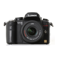
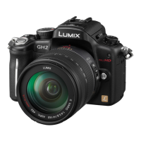
Information on servicing the bundled interchangeable lenses.
Critical points to consider before and during servicing.
Information on servicing the H-HS12035 lens main block.
Precautions for handling flexible cables and connectors.
Information on controlling and using the Wi-Fi function.
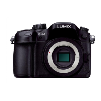
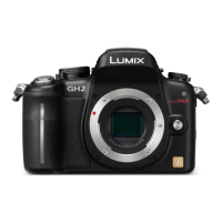
Technical data for the DMC-GH4 camera body.
Specifications related to ISO, shutter speed, and exposure.
Specifications for recording quality, file formats, and media.
Physical dimensions, operating conditions, and wireless transmitter specs.
Labeling of buttons, dials, and connectors on the camera body.
Procedure to display and access stored error codes.
A comprehensive list of error codes and their meanings.
Explains the meaning of specific indicators within the error code list.
Common problems and checks for the camera body and lenses.
Specific steps to troubleshoot focus-related issues.
Troubleshooting steps for flash and exposure malfunctions.
Explains menu options accessible via the drive mode dial.
How the tilt sensor works and the procedure for recalibration.
Steps to test the G-sensor's functionality and data output.
Method to test the power circuit of the battery grip.
Procedures to test the functionality of buttons and dials on the grip.
Steps to reset Wi-Fi password protection on the unit.
Catalog of required fixtures and tools for maintenance.
Necessary adjustments after replacing the main P.C.B.
A list of extension cables used for servicing parts.
A flowchart detailing the sequence for camera body disassembly.
Diagrams showing the locations of various PCBs within the camera.
Step-by-step guide for removing the rear case unit.
Step-by-step guide for removing the main P.C.B.
Procedure for removing the heat radiation plate unit.
Procedure for removing the front grip L unit.
Procedure for disassembling and removing the top case unit.
Steps for removing the battery case and capacitor P.C.B. unit.
Procedure for removing the Wi-Fi NFC P.C.B. and NFC unit.
Procedure for removing the tripod unit and Wi-Fi BG FPC.
Steps for disassembling and removing the mount box unit.
Procedure for removing the front grip R unit.
Steps for removing the MR1 Switch FPC unit and LCD unit.
Procedure for disassembling the LCD unit.
Procedure for disassembling the LCD IF P.C.B.
Steps for carefully removing the LCD packing.
Procedure for removing the rear operation unit and speaker.
Notes regarding button configuration and rear unit installation.
Procedure for removing the LCD lock holder unit.
Procedure for removing the SD card door unit.
Steps for disassembling the focus mode lever unit.
Procedure for disassembling the LVF module and LVF unit.
Steps for removing the EXT Mic P.C.B. unit.
Steps for removing the Flash P.C.B. unit.
Procedure for removing the flash case top.
Refers to separate manuals for lens disassembly and assembly.
A table correlating replaced parts with required adjustments.
Notes on specific adjustments like AWB, G-sensor, NFC initialization.
Procedures for cleaning the camera body, sensor, and LVF unit.
A high-level block diagram of the entire camera system.
A detailed block diagram of the system control circuitry.
Block diagram detailing the video and audio processing circuits.
Continuation of the video and audio processing circuitry block diagrams.
Block diagram illustrating the lens control and interface system.
Block diagram showing the flash and hot shoe circuitry.
Block diagram of the primary power supply circuits.
Block diagram detailing secondary power supply and regulation circuits.
A comprehensive diagram showing how all major units are interconnected.
| Camera Type | Mirrorless |
|---|---|
| Lens Mount | Micro Four Thirds |
| Autofocus Points | 49 |
| Continuous Shooting | 12 fps |
| Video Recording | 4K UHD (3840 x 2160) at 30p/24p, Full HD (1920 x 1080) at 60p/30p/24p |
| Sensor Size | 17.3 x 13.0 mm (Four Thirds) |
| Effective Pixels | 16.05 MP |
| Image Sensor Format | Four Thirds |
| ISO Sensitivity | 200-25600 (expandable to 100-25600) |
| Shutter Speed | 1/8000 to 60 sec |
| File Formats | JPEG, RAW, MP4 |
| LCD Screen | 3.0" touchscreen |
| Viewfinder Type | OLED Live View Finder |
| External Flash | Hot Shoe |
| Storage Media | SD/SDHC/SDXC card |
| Connectivity | Wi-Fi, HDMI, USB 2.0 |
| Battery | Lithium-ion Battery Pack |
| Battery Life | Approx. 500 shots (CIPA standard) |
| Dimensions | 132.9 x 93.4 x 83.9 mm |
| Weight | 560 g |