2
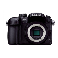
DMC-GH4HEG
Colour
(K)...........Black Type
DMC-GH4A series: Interchangeable Lens (H-HS12035) is bundled.
DMC-GH4H series: Interchangeable Lens (H-FS14140) is bundled.
TABLE OF CONTENTS
PAGE PAGE
1 Safety Precautions -----------------------------------------------3
1.1. General Guidelines ----------------------------------------3
1.2. Leakage Current Cold Check ---------------------------3
1.3. Leakage Current Hot Check (See Figure. 1) --------3
1.4. How to Discharge the E.Capacitor on
Capacitor P.C.B. Unit--------------------------------------4
2Warning--------------------------------------------------------------5
2.1. Prevention of Electrostatic Discharge (ESD)
to Electrostatically Sensitive (ES) Devices ----------5
2.2. How to Recycle the Lithium Ion Battery (U.S.
Only)-----------------------------------------------------------5
2.3. How to Replace the Lithium Battery-------------------6
2.4. Caution for AC Cord (For EB/GC/GH) ----------------7
3 Service Navigation------------------------------------------------8
3.1. Introduction --------------------------------------------------8
3.2. About Service of Bundled Lenses ---------------------8
3.3. Important Notice --------------------------------------------8
3.4. Service Notes --------------------------------------------- 12
3.5. General Description About Lead Free Solder
(PbF) -------------------------------------------------------- 14
3.6. How to Define the Model Suffix (NTSC or PAL
Model)------------------------------------------------------- 15
4 Specifications ---------------------------------------------------- 19
4.1. Camera Body---------------------------------------------- 19
4.2. Lens --------------------------------------------------------- 23
5 Location of Controls and Components------------------ 24
5.1. Camera Body---------------------------------------------- 24
5.2. Lens --------------------------------------------------------- 25
6 Service Mode ----------------------------------------------------- 26
6.1. Error Code Memory Function ------------------------- 26
7 Troubleshooting Guide---------------------------------------- 29
7.1. Checking Method of Body and
Interchangeable Lens ----------------------------------- 29
7.2. About Tilt Sensor Display ------------------------------ 34
7.3. Checking Method of Battery Grip (DMW-
BGGH3) ---------------------------------------------------- 36
7.4. Failure Diagnosis of NFC ------------------------------ 38
7.5. Wi-Fi NFC P.C.B. ---------------------------------------- 39
8 Service Fixture & Tools --------------------------------------- 40
8.1. Service Fixture and Tools ------------------------------ 40
8.2. Clean Box -------------------------------------------------- 41
8.3. When Replacing the Main P.C.B. -------------------- 41
8.4. Service Position ------------------------------------------ 42
9 Disassembly and Assembly Instructions --------------- 43
9.1. Camera Body Part--------------------------------------- 43
9.2. Disassembly and Assembly Procedure for the
Lens --------------------------------------------------------- 63
10 Measurements and Adjustments -------------------------- 64
10.1. Matrix Chart for Replaced Part and Necessary
Adjustment ------------------------------------------------ 64
11 Maintenance ------------------------------------------------------ 66
11.1. Notice in External Cleaning --------------------------- 66
12 Block Diagram --------------------------------------------------- 67
12.1. Overall Block Diagram---------------------------------- 67
12.2. System Control Block Diagram ---------------------- 68
12.3. Video/Audio Process(1) Block Diagram------------ 69
12.4. Video/Audio Process(2) Block Diagram------------ 70
12.5. Lens Block Diagram------------------------------------- 71
12.6. Flash/Hot Shoe Block Diagram ---------------------- 72
12.7. Power(1) Block Diagram------------------------------- 73
12.8. Power(2) Block Diagram------------------------------- 74
13 Wiring Connection Diagram -------------------------------- 75
13.1. Interconnection Diagram------------------------------- 75
 Loading...