45
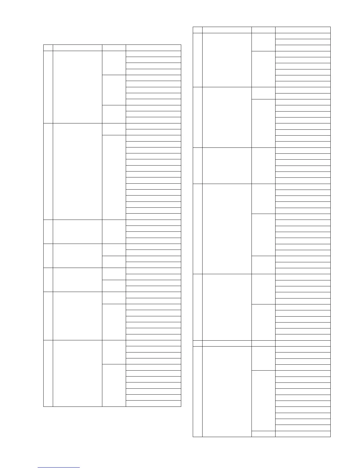
9.1.3. Disassembly Procedure
No. Item Fig. Removal
1 Rear Case Unit (Fig. D1) Memory Card
Battery
Screw (A) x 2
Screw (B) x 5
(Fig. D2) Eye Cup Unit
Screw (C) x 2
Screw (D) x 2
Screw (E) x 1
LVF DPT Knob
(Fig. D3) FP9008 (Flex)
FP9301 (Flex)
Rear Case Unit
2 Main P.C.B. (Fig. D4) Screw (F) x 2
Battery Contact Cover Unit
(Fig. D5) FP9001 (Flex)
FP9002 (Flex)
FP9003 (Flex)
FP9004 (Flex)
FP9005 (Flex)
FP9007 (Flex)
FP9009 (Flex)
FP9302 (Flex)
FP9303 (Flex)
P9003 (Connector)
Screw (G) x 2
Screw (H) x 1
Locking tab x 2
Main P.C.B.
3 Heat Radiation Plate
Unit
(Fig. D6) Screw (I) x 1
Locking tab x 2
Convex x 1
Heat Radiation Plate Unit
4 Front Grip L Unit (Fig. D7) Screw (J) x 1
Screw (K) x 1
(Fig. D8) Hooking part x 6
Front Grip L Unit
5 Top Case Unit (Fig. D9) Screw (L) x 5
Screw (M) x 1
(Fig. D10) P8501 (Connector)
Top Case Unit
6 Battery Case Unit,
Capacitor P.C.B. Unit
(Fig. D11) Screw (N) x 2
Battery Case Unit
(Fig. D12) Battery Case Sheet
Locking tab x 2
Capacitor Cover
Screw (O) x 2
Hooking part x 2
Capacitor P.C.B. Unit
7 Wi-Fi NFC P.C.B.,
NFC Unit
(Fig. D13) Connector (A)
Screw (P) x 1
Hooking part x 1
Connector (B)
(Fig. D14) Screw (Q) x 1
Locking tab x 1
Wi-Fi Holder
Wi-Fi NFC P.C.B.
Screw (R) x 1
Locking tab x 1
NFC Unit
8 Tripod,
Wi-Fi BG FPC
(Fig. D15) BG Contact Cover
IF Contact Cover
Screw (S) x 2
(Fig. D16) Screw (T) x 2
Screw (U) x 1
Tripod
Convex x 2
BG Contact Holder
Wi-Fi BG FPC
9 Mount Box Unit (Fig. D17) Screw (V) x 4
Mount Box Unit
(Fig. D18) Body Cap
Screw (W) x 2
Screw (X) x 2
B Mount
B Mount Ring
Mount Spring
Lens Lock Pin Unit
Lens Lock Pin Spring
10 Front Grip R Unit (Fig. D19) Screw (Y) x 1
Screw (Z) x 2
Hooking part x 3
Jack Cover C
Jack Cover B
Front Grip R Unit
11 MR1 Switch FPC Unit,
LCD Unit
(Fig. D20) Screw (a) x 2
Hinge Arm Cover Top
Hinge Arm Cover Bottom
Screw (b) x 4
Hinge Packing Cover Unit
(Fig. D21) Connector (C)
Solder (2 points)
Convex x 7
MR1 Switch FPC Unit
Convex x 2
Hinge Cushion 4
Hinge Fix Cover
(Fig. D22) Screw (c) x 2
Spacer x 2
LCD Unit
12 LCD IF P.C.B. (Fig. D23) Screw (d) x 2
Screw (e) x 4
Locking tab x 6
FP7200 (Flex)
LCD Case Bottom Unit
(Fig. D24) FP7202 (Flex)
LCD Hinge Unit
FP7201 (Flex)
Convex x 1
Hooking part x 1
LCD IF P.C.B.
13 LCD Packing (Fig. D25) LCD Packing
14 Rear Operation Unit,
Speaker
(Fig. D26) Screw (f) x 8
Screw (g) x 1
Screw (h) x 1
Sheet
(Fig. D27) Hooking part x 4
Rear Operation Unit
Speaker
Q.MENU Button
DISP. Button
FN3 Button
Rear Button Packing B
Rear Button Packing D x 2
Motion Picture Button
FN4 Button
(Fig. D28) When Installing
No. Item Fig. Removal
 Loading...