46
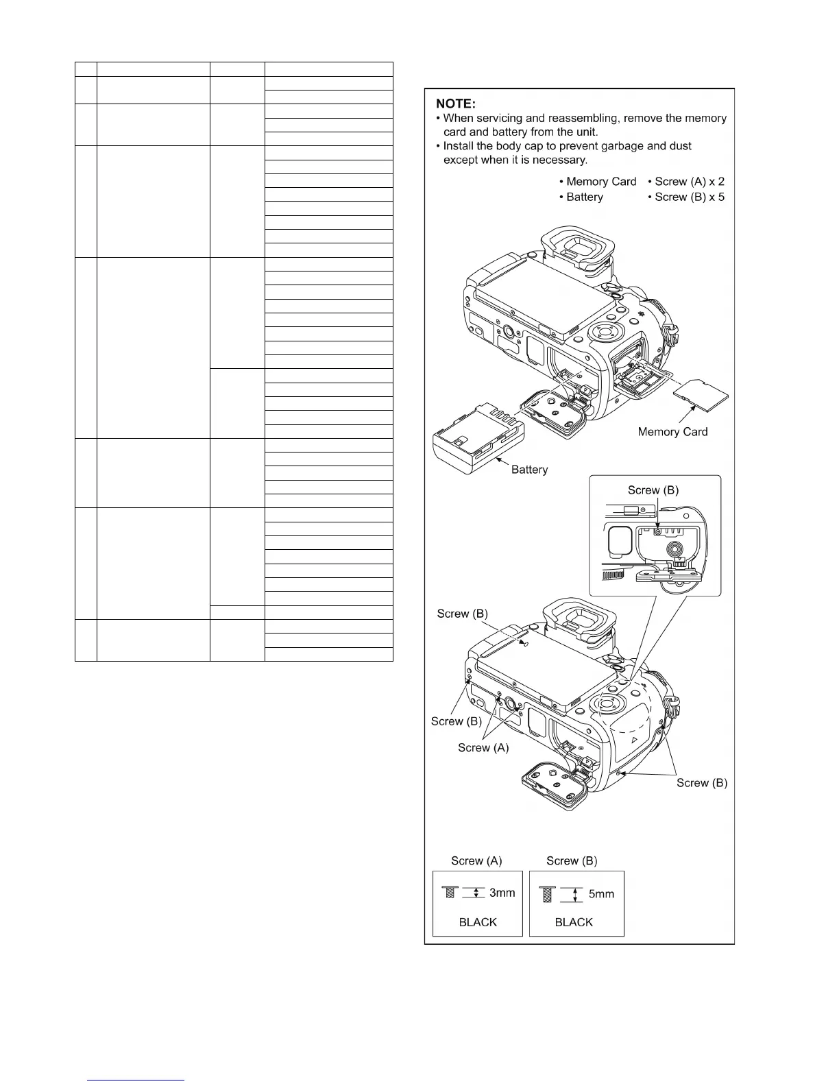
9.1.3.1. Removal of the Rear Case Unit
(Fig. D1)
15 LCD Lock Holder Unit (Fig. D29) LCD Lock Holder Unit
LCD Lock Spring
16 SD Door Unit (Fig. D30) Screw (i) x 2
Screw (j) x 3
SD Door Unit
17 Focus Mode Lever Unit,
AF/AE Lock Button
(Fig. D31) Screw (k) x 2
Rear Button Cover
Click Ball
Mode Dial Spring
E Ring
AF/AE Rotor
Focus Mode Lever Unit
AF/AE Lock Button
18 LVF Module,
LVF Unit
(Fig. D32) Screw (m) x 1
Screw (n) x 1
Screw (o) x 2
Convex x 1
Locking tab x 2
LVF Holder Tape
LVF Holder
Locking tab x 4
(Fig. D33) Heat Radiation Pad (A)
LVF Module Plate
Heat Radiation Pad (B)
LVF Module
LVF Unit
19 Ext Mic P.C.B. Unit (Fig. D34) Screw (p) x 1
FP4401 (Flex)
Solder (2 points)
Mic Jack Cover
Ext Mic P.C.B. Unit
20 Flash P.C.B. Unit (Fig. D35) Screw (q) x 3
FP8502 (Flex)
FP8503 (Flex)
FP8504 (Flex)
P8502 (Connector)
Solder (2 points)
Flash P.C.B. Unit
(Fig. D36) When Replacing
21 Flash Case Top (Fig. D37) Screw (r) x 2
Projection part x 2
Flash Case Top
No. Item Fig. Removal
 Loading...