Do you have a question about the Panasonic DMR-BWT720EB and is the answer not in the manual?
Provides general safety guidelines for servicing procedures.
Procedures for performing cold and hot leakage current checks.
Techniques to prevent component damage from electrostatic discharge.
Safety precautions for handling the laser diode.
Guidance on using lead-free solder for repairs.
Connecting, disconnecting, and registering external HDDs.
Steps to format the HDD after replacement or error.
Using remote combinations to enter special operation modes.
Overview of entering service and disclosure modes.
Procedure to check the conduction of the micro fuse.
Methods for checking HDD and BD drive malfunctions.
Checking the operation status of connected USB devices.
Procedures for checking Wi-Fi module settings and status.
Using tuner service mode for hard tests and inspections.
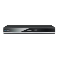
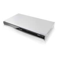
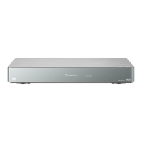
Identification of controls and components on the main unit.
Procedure for forced disc ejection if the unit fails.
Step-by-step guide for disassembling and assembling the unit.
Flowchart and PCB positions for unit disassembly.
Instructions for removing the BD drive.
Steps for disassembling the BD drive unit.
Procedure for cleaning the optical pick-up lens.
Procedures for measurements and adjustments during service.
Steps for checking and repairing the Main PCB.
Steps for checking and repairing the AV IO PCB.
Steps for checking and repairing the Digital PCB.
Important notes and procedures after replacing parts.
Inspection criteria to verify normal operation post-repair.
Visual representations of the unit's internal circuits.
Comprehensive block diagram of the unit's architecture.
Block diagram of the power supply circuit.
Block diagram of analog video signal processing.
Block diagram of analog audio signal processing.
Block diagram of the timer and control circuits.
Block diagram showing regulators on the Digital PCB.
First part of the digital block diagram.
Second part of the digital block diagram.
Schematic showing interconnections between unit components.
Detailed schematic of wiring between PCBs and modules.
Exploded view of the unit's frame and casing components.
Further exploded view of frame and casing components.
Exploded view illustrating the components of the drive mechanism.
| Storage Capacity | 500 GB |
|---|---|
| Video Output | HDMI |
| 3D Playback | Yes |
| Smart Features | Yes |
| Wi-Fi | Yes |
| USB Ports | 2 |
| Twin Tuner | Yes |
| Ethernet | Yes |
| DLNA Certified | Yes |
| Supported Disc Formats | BD-RE, BD-R, DVD-R, DVD-RW, DVD+R, DVD+RW, CD, CD-R, CD-RW |
| Video Formats | MPEG-2, AVCHD |
| Audio Formats | Dolby Digital, Dolby Digital Plus, Dolby TrueHD, DTS, DTS-HD Master Audio |
| Output Resolution | 1080p |
| Dimensions (W x H x D) | 430 x 59 x 199 mm |
| Type | Blu-ray Disc Recorder |
| Region Code | Blu-ray: B, DVD: 2 |