11
Parts identication
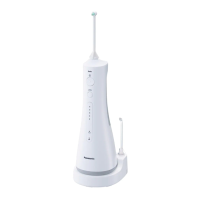
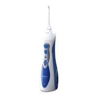
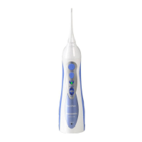
A
Handle
1
Stop/Jet switch
2
Jet mode
3
Stop
4
Nozzle release button
5
Nozzle
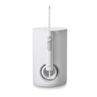
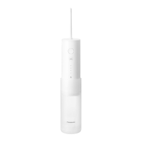
B
Main body
6
Cord
7
Power plug
8
Suction hose
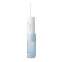
C
Water tank
9
Upper water level limit
Water tank cap
D
Operation panel
Water pressure
level LED indicator
(1~10 levels)
Power switch
Water pressure
regulator switch
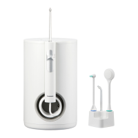
E
Nozzle (x2)
• Thenozzleisa
consumable.
Identicationring
(white & blue)
Accessory
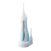
F
Nozzle stand
There may be moisture inside
the main unit (water tank
and suction hose) left from
the distilled water used for
product testing.
How to use
On sink or shelf
1
Placethemainunitonaatandstable
surface.
2
Plug in the power plug.
•Convenientdualpowercord
outlet able to pull out the
cord, both right and left.
1. Open the water tank cap, remove
the water tank, and ll it with water.
•Alwaysusenewtapwaterorlukewarm
water.
•Ifthewaterfeelscold,uselukewarm
water with a temperature of 40 °C or less.
•Whenllingwater,besurenottoexceed
the upper water level limit.
level limit
2. Set the tank to the main unit rmly,
and attach the water tank cap.
3. Insert the nozzle rmly into the
handle. Make sure xed rmly.
PB014248 - EW1611W503 ������_(01EN)_01-20-17.indd 11 2017/1/20 14:59:24