Boolean
Ladder Diagram
Address Instruction
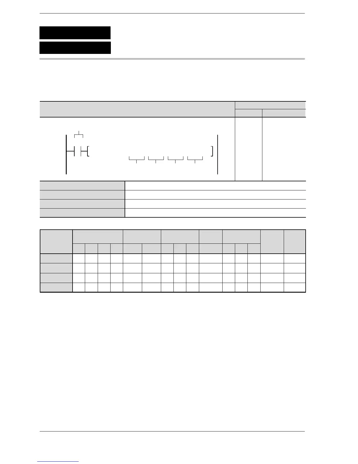
S1
Trigger
S3S2 D
F347 FLIMT, DT10, DT20, DT30, DT4010
R0
10
11
ST R 0
F347 (FLIMT)
DT 10
DT 20
DT 30
DT 40
S1 The area where the lower limit is stored or the lower limit data. (2 words)
S2 The area where the upper limit is stored or the upper limit data. (2 words)
S3 The area where the input value is stored or the input value data. (2 words)
D The area where the output value is stored. (2 words)
Operands
O
WX WY WR WL SV EV DT LD FL I K H f
modifier device
S1 A A A A A A A A A A A A A A* A
S2 A A A A A A A A A A A A A A* A
S3 A A A A A A A A A A A A A A* A
D N/A A A A A A A A A A N/A N/A N/A A A
* Index modification of a real number is not possible.
Description
The output value (real number data) stored in the area specified by D is controlled based on whether or not
the input value (real number data) specified by S3 falls within the range bounded by the upper and lower limits
(real number data) set in S1 and S2.
The output value is determined based on the following conditions:
When the lower limit S1+1 and S1 are greater than the input value S3+1 and S3, the lower limit value S1+1
and S1 stored in D+1 and D as the output value.
When the upper limit S2+1 and S2 are less than the input value S3+1 and S3, the upper limit value S2+1 and
S2 are stored in D+1 and D as the output value.
F347
P347
(PFLIMT)
(FLIMT)
Floating point data upper and lower limit control





 To Next Page