EasyManua.ls Logo

Panasonic FP-E - Page 1040

Panasonic FP-E
1334 pages
Print Icon
To Next Page IconTo Next Page
To Previous Page IconTo Previous Page
Loading...
High−level Instructions
3 − 776
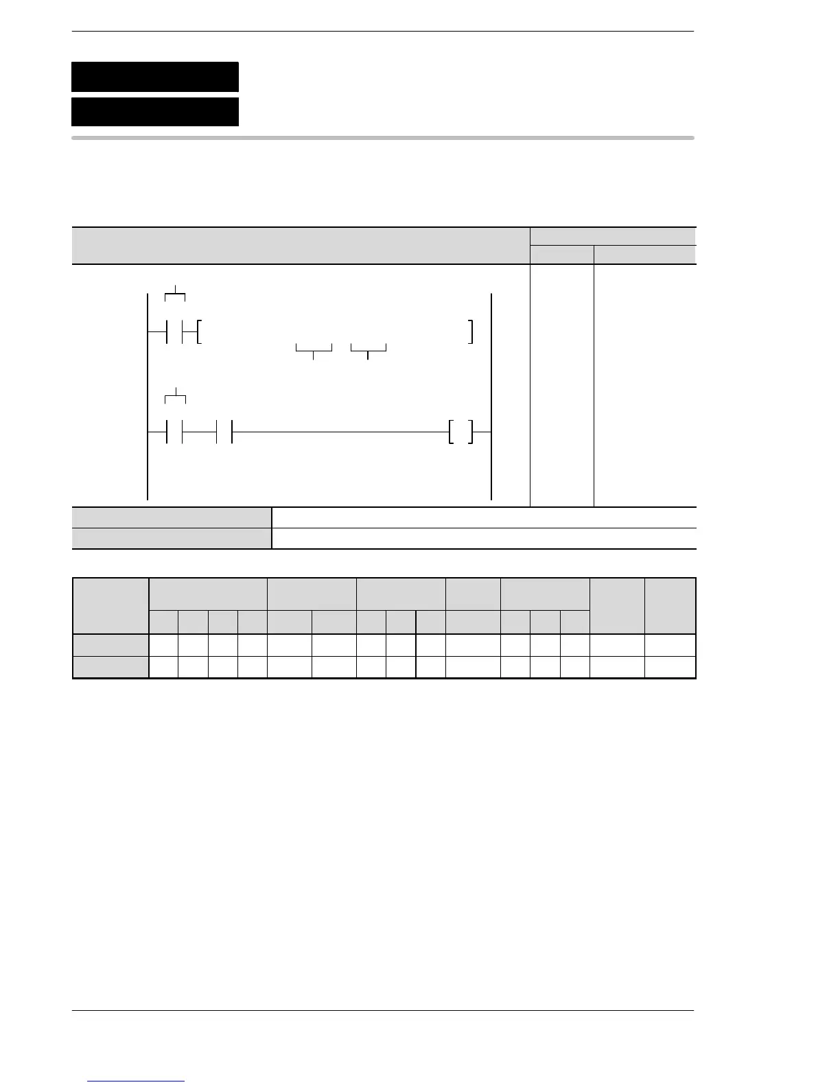
Outline This instruction detects changes in 16-bit data values.
Program example
Ladder
Diagram
Boolean
Ladder Diagram
Address Instruction
S
Trigger
D
F373 DTR, DT10, DT20
10
R0
17
R0 R10
R9009
Trigger
10
11
17
18
20
ST R 0
F373 (DTR)
DT 10
DT 20
ST R 0
AN R9009
OT R 10
S 16-bit area for detecting data changes.
D Area where data of previous execution is stored.
Operands
O
p
erand
Relay Timer/Counter Register
Index
register
Constant
Index
modifier
Integer
device
Operand
WX WY WR WL SV EV DT LD FL I K H f
modifier device
S A A A A A A A A A A N/A N/A N/A A N/A
D N/A A A A A A A A A A N/A N/A N/A A N/A
Explanation of example
When the trigger R0 turns on, R9009 will turn on if there has been a change in data register DT10 since the
previous execution. Following this, the internal relay R10 will also turn on.
Description
If the data in the 16-bit area specified by S has changed since the previous execution, internal relay R9009
(carry flag) will turn on.
D is used to store the data of the previous execution, and when the current execution has been completed,
the current data is stored in D.
F373
P373
(PDTR)
(DTR)
16-bit data revision detection
A
:
A
vailable
N/A: Not Available
Phone: 800.894.0412 - Fax: 888.723.4773 - Web: www.clrwtr.com - Email: info@clrwtr.com