Basic Instructions
2 − 97
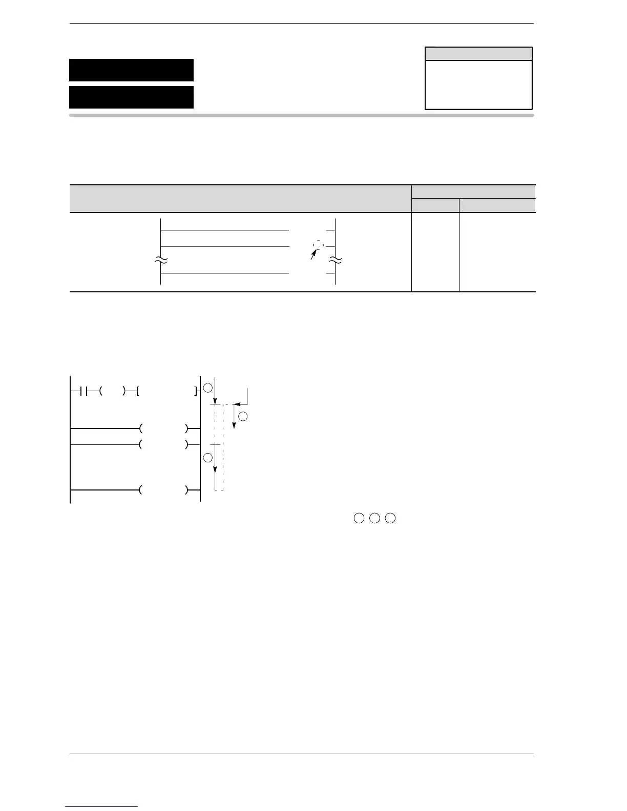
Outline INT: Indicates the start of the interrupt program.
IRET: Indicates the end of the interrupt program.
Program example
Boolean
Ladder Diagram
Address Instruction
Interrupt program number
20
21
26
(INT 0 )
(ED )
(IRET )
20
21
26
....
ED
INT 0
IRET
....
Description
When an interrupt is input, the interrupt program of the number specified is executed starting from the INT
instruction.
When the interrupt program reaches the IRET instruction, the program returns to the address where the
interrupt occurred and the main program resumes.
ED
INT n
IRET
DF
X0
Interrupt
program n
ICTL, S1, S2
Main program
Interrupting
1
2
3
When the interrupt occurs, the program is executed in the order
1
−
2
−
3
shown above.
In the default mode, all interrupt programs are disabled and cannot be executed. The ICTL instruction should
be used to enable execution of an interrupt program.
Syntax of interrupt program
An interrupt program n (n: 0 to 24) is the program between the INTn instruction and the IRET instruction. The
interrupt program must always be placed after the ED instruction. Up to 25 programs can be written.
The number of the interrupt program is decided by the type of the interrupt.
INT0 to INT15: Interrupts from the interrupt unit
INT16 to INT23: Interrupts from an intelligent unit that issues interrupts
INT24: Periodic interrupt
FP2/FP2SH/FP10SH
INT
IRET
Interrupt
Interrupt return
Availability
FP2/FP2SH/FP10SH







 To Next Page