Boolean
Ladder Diagram
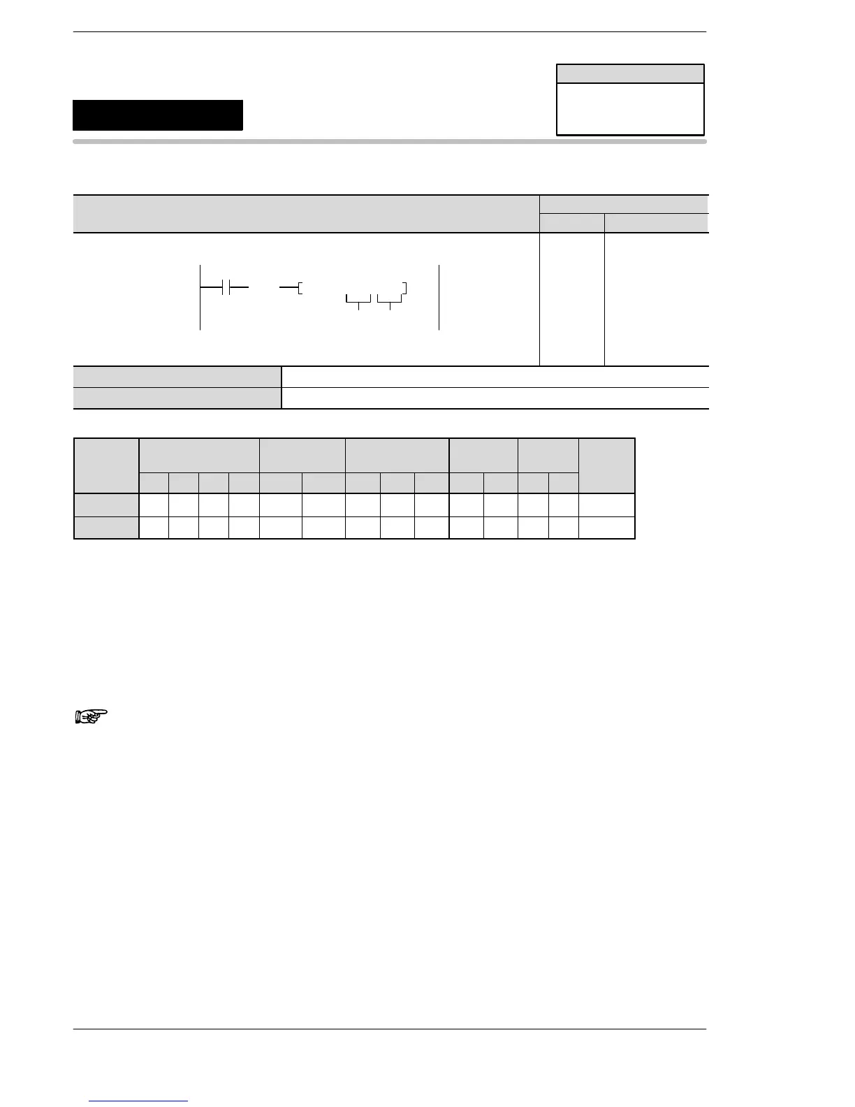
Address Instruction
X10
0
(DF )
ICTL, H 0, H 1
S1 S2
0
1
2
ST X 10
DF
ICTL
H0
H1
S1 16-bit equivalent constant or 16-bit area for interrupt control data setting
S2 16-bit equivalent constant or 16-bit area for interrupt condition setting
Operands
O
WX WY WR WL SV EV DT LD FL IX IY K H
modifier
S1 A A A A A A A A A A A A A A
S2 A A A A A A A A A A A A A A
Description
When the ICTL instruction is executed, the interrupt program enable/disable and interrupt clear are set
according to the settings in S1 and S2.
Be sure to use ICTL instructions so that they are executed once at the leading edge of the execution condition
(trigger) using the DF instruction.
Two or more ICTL instructions can have the same execution condition (trigger).
Note
Before executing an interrupt program, be sure to execute the
ICTL instruction and enable the execution of the interrupt
program.
FP0/FP0R/FP−e/FPΣ/FP−X
FP0/FP−e/FPΣ/FP−X/
FP0R
ICTL
Availability
Interrupt control
A: Available







 To Next Page