WX WY WR WL SV EV DT LD FL I K H M
modifier
S N/A N/A N/A N/A N/A N/A N/A N/A N/A N/A N/A N/A A N/A
Explanation of example
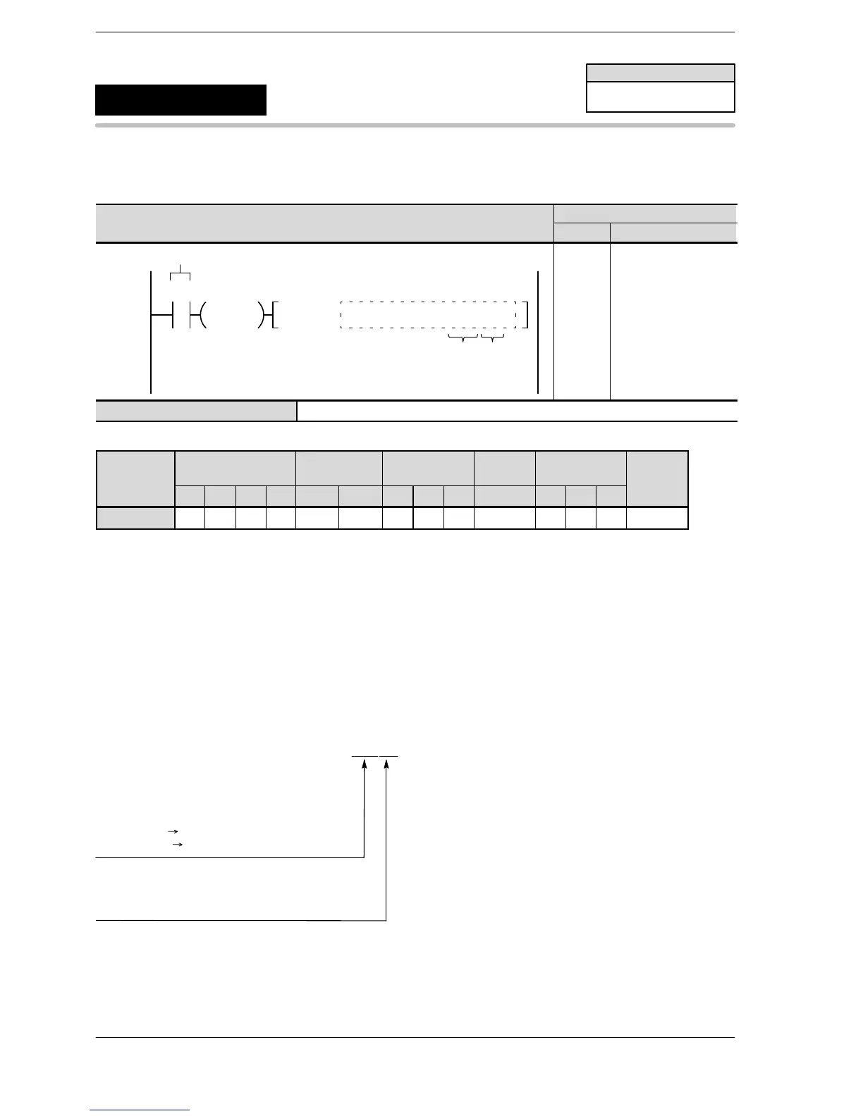
When R0 turns on, input X1 is set to the interrupt that becomes valid at the rising edge.
Description
This sets the input specified by No. 1 keyword as the interrupt input, and changes the input conditions to the
contents specified by No. 2 keyword.
Keyword setting
SYS1, M INT2,UP
Interrupt input
INT0: X0 INT1: X1
INT2: X2 INT3: X3
INT4: X4 INT5: X5
INT6: X6 INT7: X7
INT8 − INT10 Pulse I/O cassette 1
INT11 − INT12 Pulse I/O cassette 2
Effective edges
UP: Rising edge
DOWN: Falling edge
BOTH: Rising and falling edges
INT8: X0 INT9: X1
INT10: X2 INT11: X3
INT12: X4 INT13: X5
FPΣ/FP−X/FP0R
SYS1
Availability
FPΣ/FP−X/FP0R
Interrupt setting
A: Available
N/A: Not Available






 To Next Page