Basic Instructions
2 − 129
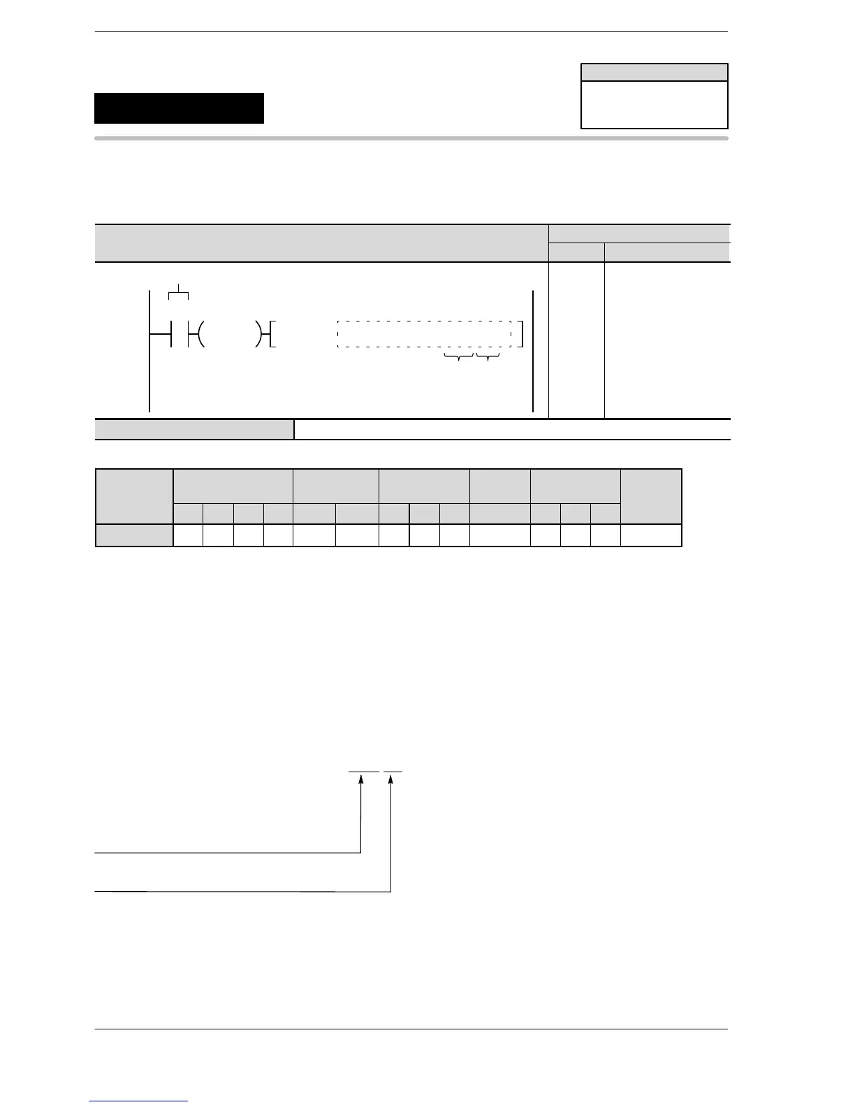
Outline This changes the operation mode of the high−speed counter based on
the contents specified by the character constant.
Program example
WX WY WR WL SV EV DT LD FL I K H M
modifier
S N/A N/A N/A N/A N/A N/A N/A N/A N/A N/A N/A N/A A N/A
Explanation of example
When R0 turns on, the operation mode of the high−speed counter CH0 is set to the addition mode.
Description
This changes the operation mode of the high−speed counter specified by No.1 keyword to the operation
mode specified by No.2 keyword.
Keyword setting
SYS1, M HSC1,UP
High−speed counter setting
HSCn n: 0 to 9, A, B with FP−X Ry type
n: 0 to 7 with FP−X Tr type
n: 0, 1, 2, 3 with FPΣ
n: 0, 1, 2, 3, 4, 5 with FP0R
UP: Addition input setting
DOWN: Subtraction input setting
FPΣ/FP−X/FP0R
SYS1
Availability
FPΣ 32k
FP−X Ver 1.10 or more
FP0R
Change high−speed counter
operation mode
A: Available
N/A: Not Available






 To Next Page