Basic Instructions
2 − 151
Eplanation of example
Compares the contents of data registers (DT1, DT0) with the data registers (DT101, DT100). When X0 turns
on or if (DT1, DT0)
(DT101, DT100), the external output relay Y30 goes on.
If (DT1, DT0) < (DT101, DT100) and if X0 is in the off state, the external output relay Y30 goes off.
Description
Compares the double word data specified by S1 and S1+1 with the double word data specified by S2 and
S2+1 according to the comparison condition.
The ORD instruction results in parallel connection as the liaison contact when the comparison result is a
specified status (=, >, <, etc.).
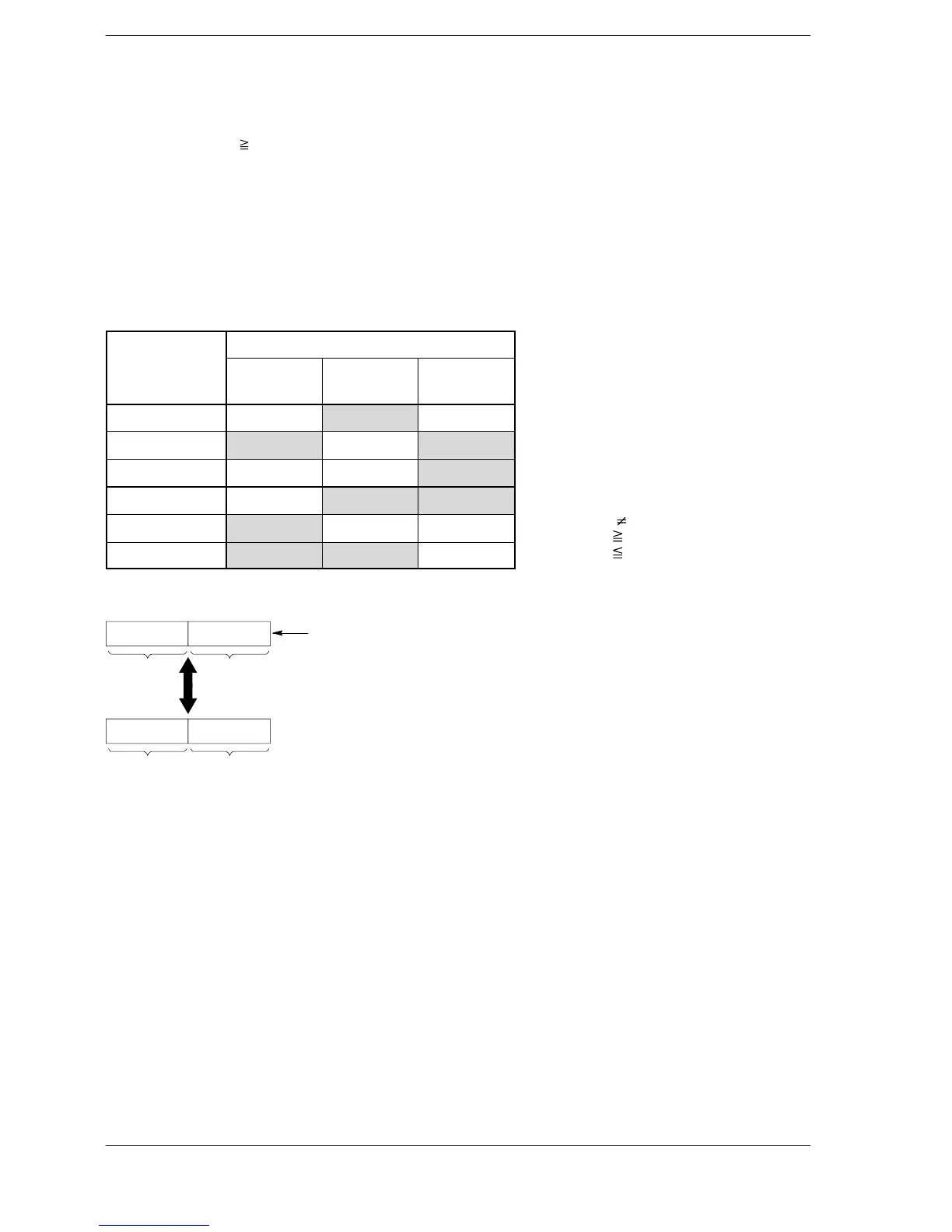
The result of the comparison operation is as follows:
Comparison
Condition
instruction
(S1+1, S1)<
(S2+1, S2)
(S1+1, S1) =
(S2+1, S2)
(S1+1, S1) >
(S2+1, S2)
ORD= off on off
ORD<> on off on
ORD> off off on
ORD>= off on on
ORD< on off off
ORD<= on on off
When processing 32-bit data, the higher 16-bit areas (S1+1, S2+1) are automatically determined once the
lower 16-bit areas (S1, S2) are specified.
S1S1+1
S2S2+1
Comparison
The specified data area and the following data area are handled
together as 32−bit data.
Precautions concerning usage
The OR comparison instructions ORD =, ORD <>, ORD >, ORD >=, ORD <, and ORD <= are programmed
from the bus line.
Multiple OR comparison instructions ORD =, ORD <>, ORD >, ORD >=, ORD<, and ORD <= can be used
consecutively.
If mixed with BCD or other type of data, the value will be regarded as negative when the most significant bit is 1
and a correct comparison may not be obtained. In this case, use an F83 (DBIN) instruction or similar
instruction to change the data to binary data before making the comparison.
Flag conditions
・Error flag (R9007): Turns on and stays on when the area specified using the index modifier
exceeds the limit.
・Error flag (R9008): Turns on for an instant when the area specified using the index modifier
exceeds the limit.
< > indicates
>= indicates
<= indicates








 To Next Page