High−level Instructions
3 − 25
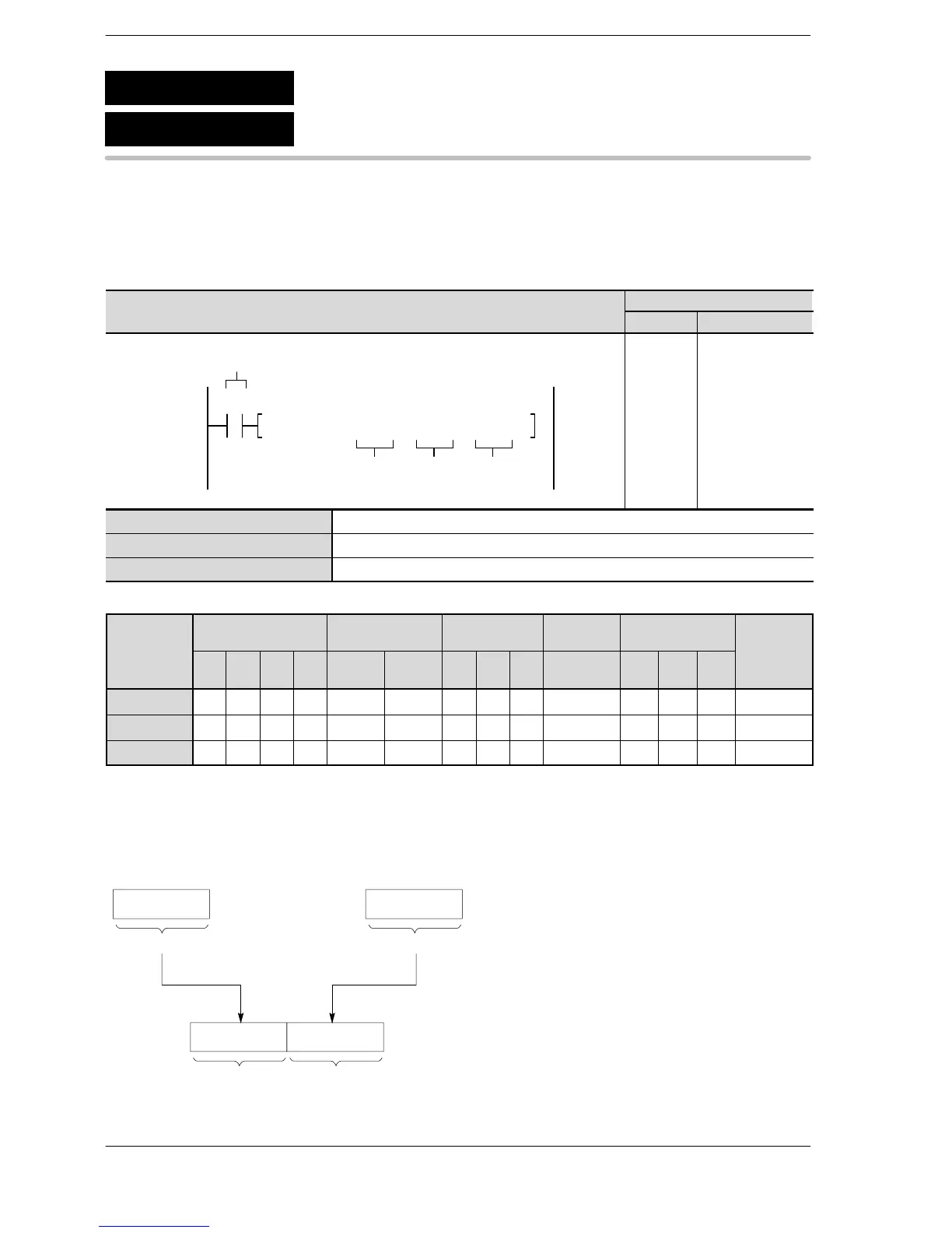
Outline Copies two 16-bit data to the specified 32-bit area.
For the FP0R/FPΣ/FP−X, the P type high−level instruction “P7 (PMV2)”
is not available.
Program example
Boolean
Ladder Diagram
Address Instruction
F7 MV2, DT10, DT20, DT3010
R0
S2 DS1
Trigger
10
11
ST R 0
F7 (MV2)
DT 10
DT 20
DT 30
S1 16-bit equivalent constant or 16-bit area (source)
S2 16-bit equivalent constant or 16-bit area (source)
D Lower 16-bit area for 32-bit area (destination)
Operands
Relay T imer/Counter Register
Index
register
Constant
Inde
Operand
WX WY WR WL SV EV DT LD
FL
(*1)
I K H f
modifier
S1 A A A A A A A A A A A A N/A A
S2 A A A A A A A A A A A A N/A A
D N/A A A A A A A A A A N/A N/A N/A A
(*1) This cannot be used with the FP0R, FPΣ and FP−X.
Explanation of example
The contents of data register DT10 are copied to data register DT30 when trigger R0 turns on.
The contents of data register DT20 are copied to data register DT31 when trigger R0 turns on.
Contents of DT20
DT30DT31
16 bits 16 bits
Contents of DT10
[S2]
[D]
[S1]
F7
P7
Two 16-bit data move
(MV2)
(PMV2)
vailable
N/A: Not Available
Phone: 800.894.0412 - Fax: 888.723.4773 - Web: www.clrwtr.com - Email: info@clrwtr.com






 To Next Page