modifier
S A A A A A A A A A N/A N/A N/A N/A A
(*1) With the FP2SH/FP10SH, this is I0 to IC.
(*2) With the FP2SH/FP10SH, this is ID.
Explanation of example
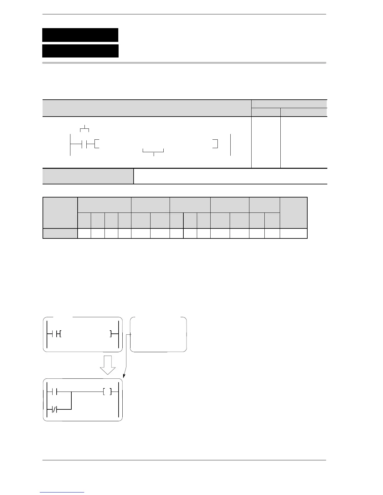
When the execution condition R0 is on, the programs for file names written to data register DT100 and
subsequent data registers are read from the IC memory card, and are substituted for the program currently
being executed.
If “STEP2” is written for data register DT100 or a subsequent register, the program with the file name “STEP2”
stored on the IC memory card is read.
RUN mode
R0 : on
DT100: “STEP2”
R0
F14(PGRD) , DT100
・ Program “STEP1”
・ Program “STEP2”
・ Program “STEP3”
R20
Y40
R21
The program “STEP2”
is executed.
CPU IC memory card
F14
P14
Program read from IC card
(PGRD)
(PPGRD)
A: Available
N/A: Not Available





 To Next Page