High−level Instructions
3 − 127
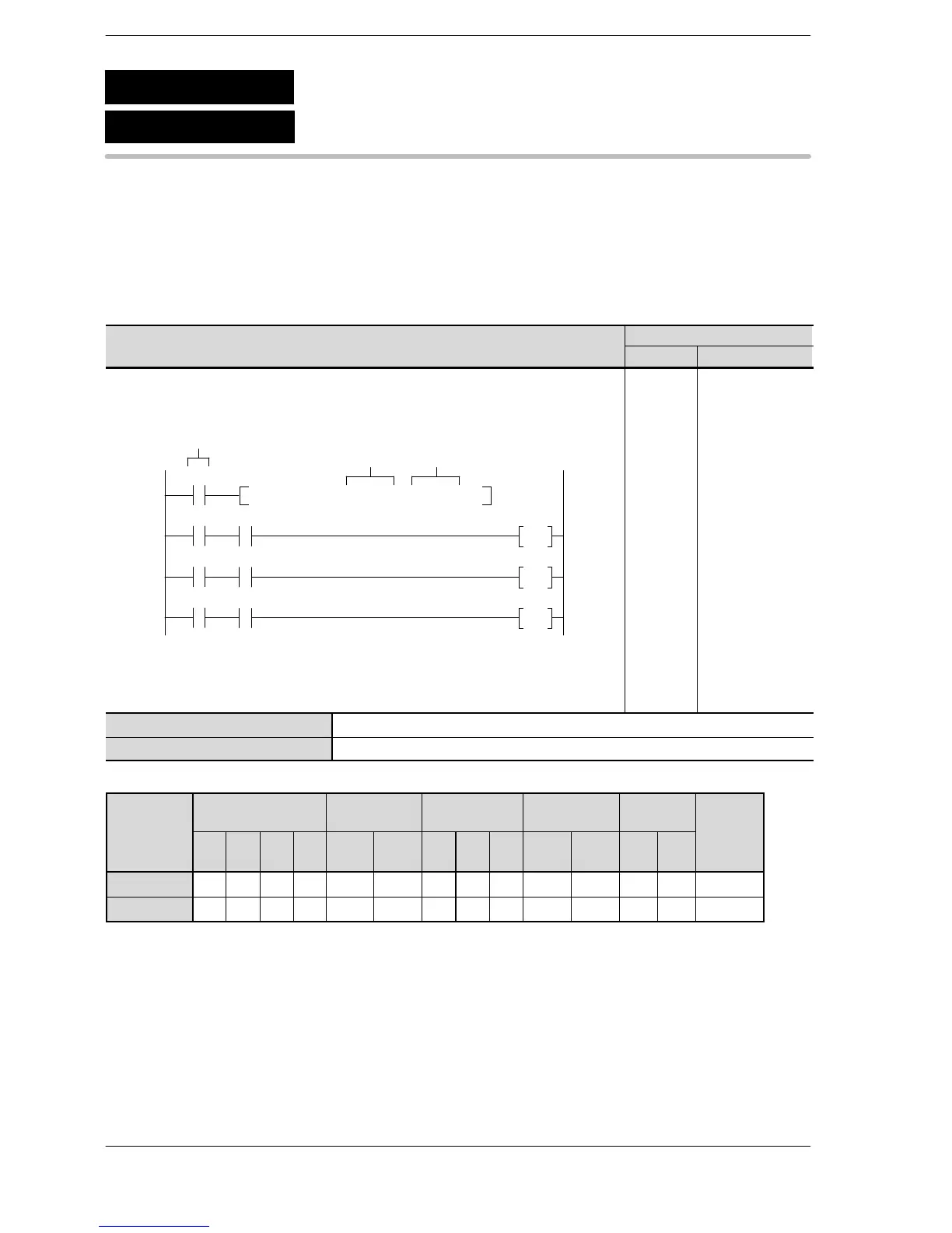
Outline The two specified 16−bit data are compared and the result is output to
the special internal relay.
For the FP0R/FPΣ/FP−X/FP0/FP−e, the P type high−level instruction
“P60 (PCMP)” is not available.
Program example
Boolean
Ladder Diagram
Address Instruction
40
F60 CMP , DT 0 , K 100
46
49
52
R900A
R900B
R900C
Trigger
S1 S2
Y10
Y11
Y12
R0
R0
R0
R0
40
41
46
47
48
49
50
51
52
53
54
ST R 0
F60 (CMP)
DT 0
K 100
ST R 0
AN R 900A
OT Y 10
ST R 0
AN R 900B
OT Y 11
ST R 0
AN R 900C
OT Y 12
S1 16-bit equivalent constant or 16-bit area to be compared
S2 16-bit equivalent constant or 16-bit area to be compared
Operands
modifier
S1 A A A A A A A A A A A A A A
S2 A A A A A A A A A A A A A A
(*1) This cannot be used with the FP0 and FP−e.
(*2) This cannot be used with the FP0, FP−e, FP0R, FPΣ, FP−X.
(*3) With the FP0R, FPΣ,FP−X, FP2, FP2SH, and FP10SH, this is I0 to IC.
(*4) With the FP0R, FPΣ,FP−X, FP2, FP2SH, and FP10SH, this is ID.
F60
P60
(PCMP)
(CMP)
16-bit data comparison
A: Available





 To Next Page