High−level Instructions
3 − 138
Explanation of example
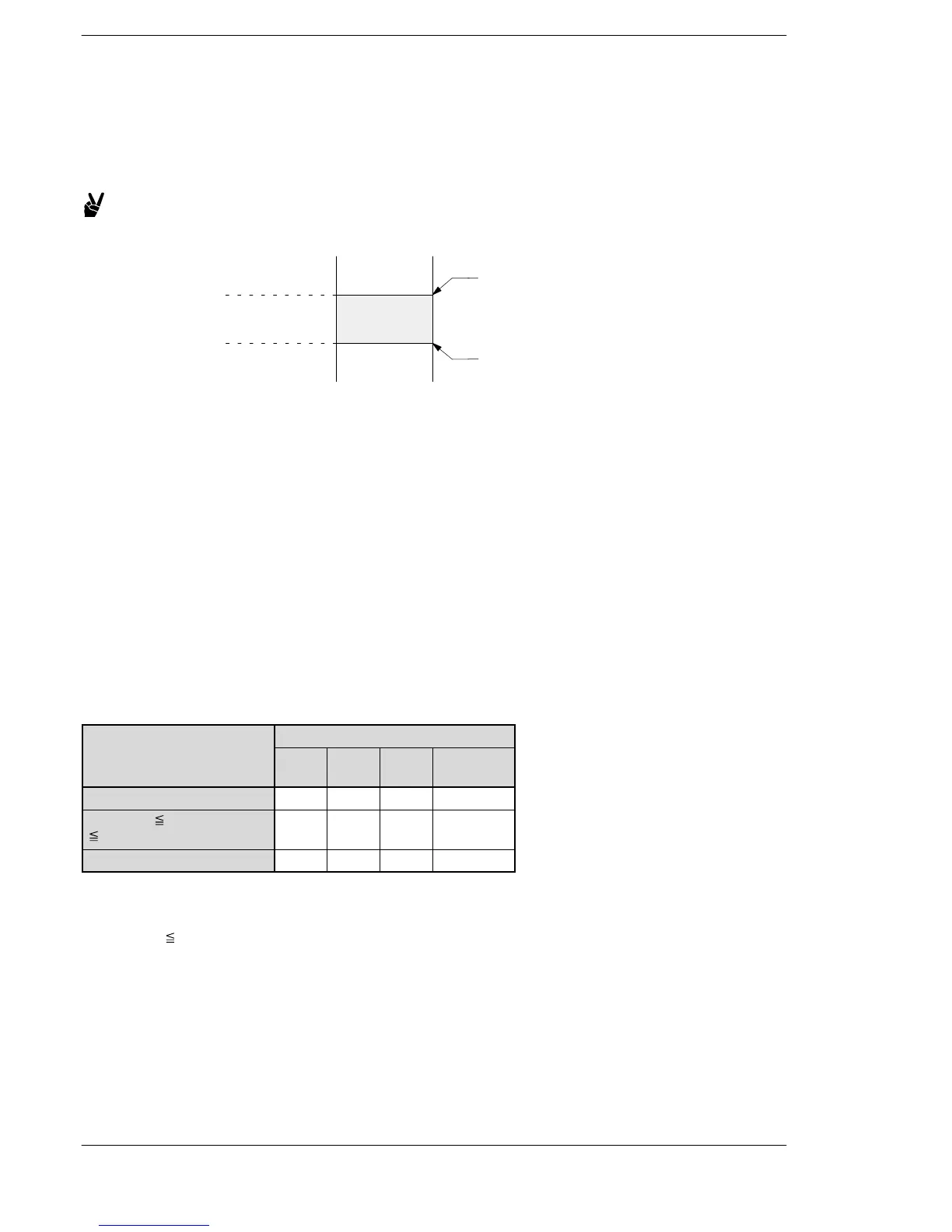
Compares the contents of data registers DT11 and DT10 with the contents of data registers DT21 and DT20
(lower limit of the data band) and data registers DT31 and DT30 (upper limit of the data band), when trigger R0
turns on.
Example: When K−50000 is in DT21 and DT20 and K50000 is in DT31 and
DT30, as shown below.
R900A : on
R900B : on
R900C : on
+50000
−50000
When (DT11, DT10) is K−68000, R900C turns on and external
output relay Y12 goes on.
When (DT11, DT10) is K−50000, R900B turns on and external
output relay Y11 goes on.
When (DT11, DT10) is K25600, R900B turns on and external
output relay Y11 goes on.
When (DT11, DT10) is K68000, R900A turns on and external
output relay Y10 goes on.
Description
Compares the 32-bit equivalent constant or 32-bit data specified by S1 with the data band specified by S2
and S3. This instruction checks whether S1 is in the data band between S2 (lower limit) and S3 (upper limit),
larger than S3, or smaller than S2. The comparison result is output to the special internal relays R9009,
R900A, R900B, and R900C.
The following table lists the states of the R9009, R900A, R900B and R900C.
Com
(S1+1, S1), (S2+1, S2)
and (S3+1, S3)
R900A
(> flag)
R900B
(= flag)
R900C
(< flag)
R9009
(carry flag)
(S1+1, S1) < (S2+1, S2)
off off on
———
(S2+1, S2) (S1+1, S1)
(S3+1, S3)
off on off
———
(S3+1, S3) < (S1+1, S1)
on off off
———
Precaution during programming
Set it so that the value of the lower limit (S2 + 1, S2) is less than the value of the upper limit (S3 + 1, S3)
[(S2+1, S2)
(S3+1, S3)].
Flag conditions
・Error flag (R9007): Turns on and stays on when:
・Error flag (R9008): Turns on for an instant when:
− The area specified using the index modifier exceeds the limit.
− (S2+1, S2) > (S3+1, S3).





 To Next Page