High−level Instructions
3 − 183
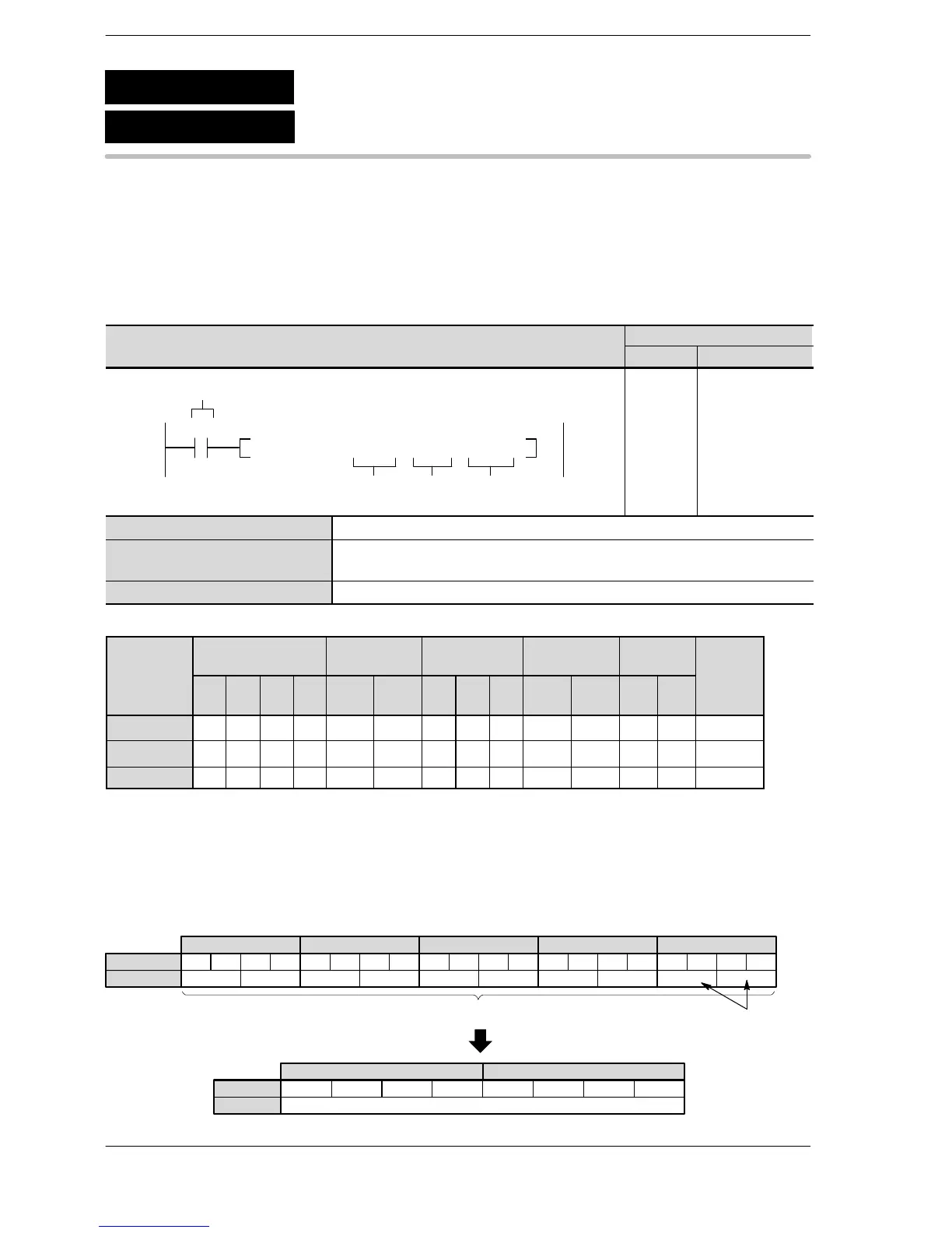
Outline Converts ASCII code that expresses decimal digits to 32-bit data that
expresses the equivalent number.
For the FP0R/FPΣ/FP−X/FP0/FP−e, the P type high−level instruction
“P78 (PDABI)” is not available.
Program example
Boolean
Ladder Diagram
Address Instruction
10
F78 DABI , DT 0 , K 10 , DT 50
S1
D
Trigger
S2
R0
10
11
ST R 0
F 78 (DABI)
DT 0
K10
DT 50
S1 Starting 16-bit area for ASCII code (source)
S2 16-bit equivalent constant or 16-bit area to specify number of source data bytes
to be converted
D Lower 16-bit area of 32-bit data for storing converted data (destination)
Operands
modifier
S1 A A A A A A A A A N/A N/A N/A N/A A
S2 A A A A A A A A A A N/A A A A
D N/A A A A A A A A A N/A N/A N/A N/A A
(*1) This cannot be used with the FP0 and FP−e.
(*2) This cannot be used with the FP0, FP−e, FP0R, FPΣ, FP−X.
(*3) With the FP0R, FPΣ,FP−X, FP2, FP2SH, and FP10SH, this is I0 to IC.
Explanation of example
Converts ASCII codes (10 bytes) that express decimal digits in data registers DT4, DT3, DT2, DT1 and DT0
to 32-bit data when trigger R0 turns on. The converted data is stored in data registers DT51 and DT50.
···
Decimal
Bit position
·····
K12345678
15 12 11 8 7 4 3 0
DT51
Source
Destination
·
·
·······
15 12 11 8 7 4 3 0
DT50
ASCII HEX code
ASCII character
3
8
83
7
7 3
6
63
5
5
DT4 DT3
ASCII codes (10 bytes) specified by S2
3
4
43
3
3 3
2
23
1
1
DT2 DT1
220
DT0
SPACE
0
F78
P78
(PDABI)
(DABI)
ASCII code → 32-bit binary data
A: Available
N/A: Not Available





 To Next Page