High−level Instructions
3 − 206
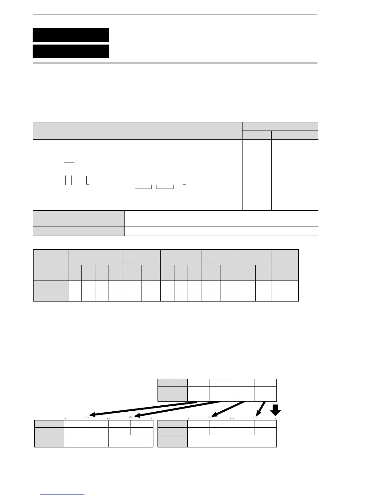
Outline Converts 16-bit data to 4-digit data for 7-segment indication.
For the FP0R/FPΣ/FP−X/FP0/FP−e, the P type high−level instruction
“P91 (PSEGT)” is not available.
Program example
Boolean
Ladder Diagram
Address Instruction
10
F91 SEGT , DT 0 , DT10
S
D
Trigger
R20
10
11
ST R 20
F 91 (SEGT)
DT 0
DT 10
S 16-bit equivalent constant or 16-bit area to be converted to the 7-segment
indication (source)
D Starting 16-bit area for storing 4-digit data for 7-segment indication (destination)
Operands
modifier
S A A A A A A A A A A A A A A
D N/A A A A A A A A A A N/A N/A N/A A
(*1) This cannot be used with the FP0 and FP−e.
(*2) This cannot be used with the FP0, FP−e, FP0R, FPΣ, FP−X.
(*3) With the FP0R, FPΣ,FP−X, FP2, FP2SH, and FP10SH, this is I0 to IC.
(*4) With the FP0R, FPΣ,FP−X, FP2, FP2SH, and FP10SH, this is ID.
Explanation of example
Converts the contents of data register DT0 to 4-digit data for 7-segment indication when trigger R20 turns on.
The converted data is stored in word internal relays DT11 and DT10.
For example, to display ”ABCD”, the following would be entered.
0111011101111100 0011100101011110
15
·· ·
Bit position
·····
DT10
15 12 11 8 7 4 3 0
7-segment
indication
CD
Destination
·· ·
Bit position
·····
DT11
1211 87 43 0
7-segment
indication
AB
Source
····
Bit position
·····
DT0
15
101
12
0
11
101
8
1
7
110
4
0
3
110
0
1
Hexadecimal
ABCD
F91
P91
(PSEGT)
(SEGT)
7-segment decode
A: Available
N/A: Not Available





 To Next Page