High−level Instructions
3 − 236
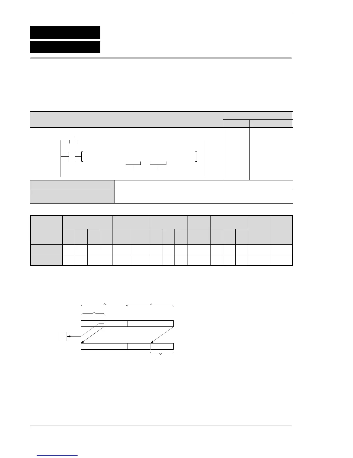
Outline Shifts a specified number of bits to the left in bit units.
For the FP0R/FPΣ/FP−X/FP0/FP−e, the P type high−level instruction
“P103 (PDSHL)” is not available.
Program example
Boolean
Ladder Diagram
Address Instruction
F103 DSHL, DT10, DT 210
R0
nD
Trigger
10
11
ST R 0
F103 (DSHL)
DT 10
DT 2
D Lower 16-bit area of 32-bit data to be shifted to the left
n 16-bit equivalent constant or 16-bit area (specifies number of shifted bits)
Range of n: K0 to K255 (H0 to HFF)
Operands
device
D N/A A A A A A A A A A N/A N/A N/A A N/A
n A A A A A A A A A A A A N/A A N/A
(*1) This cannot be used with the FP0R, FPΣ and FP−X.
Description
Shifts n bits of the 32-bit area specified by D to the left (to the higher bit position) when the trigger turns on.
15
00000000
0
[n bits]
CY
015
[D+1] [D]
[n bits] starting from bit position 0
are filled with 0s.
The data in the nth
bit is transferred to
R9009 (carry flag).
When the n bits are shifted to the left,
− The n bits starting from bit position 0 are filled with 0s.
− The data in the nth bit is transferred to special internal relay R9009 (carry flag).
F103
P103
(PDSHL)
(DSHL)
Left shift of n bits in a 32-bit data





 To Next Page