High−level Instructions
3 − 254
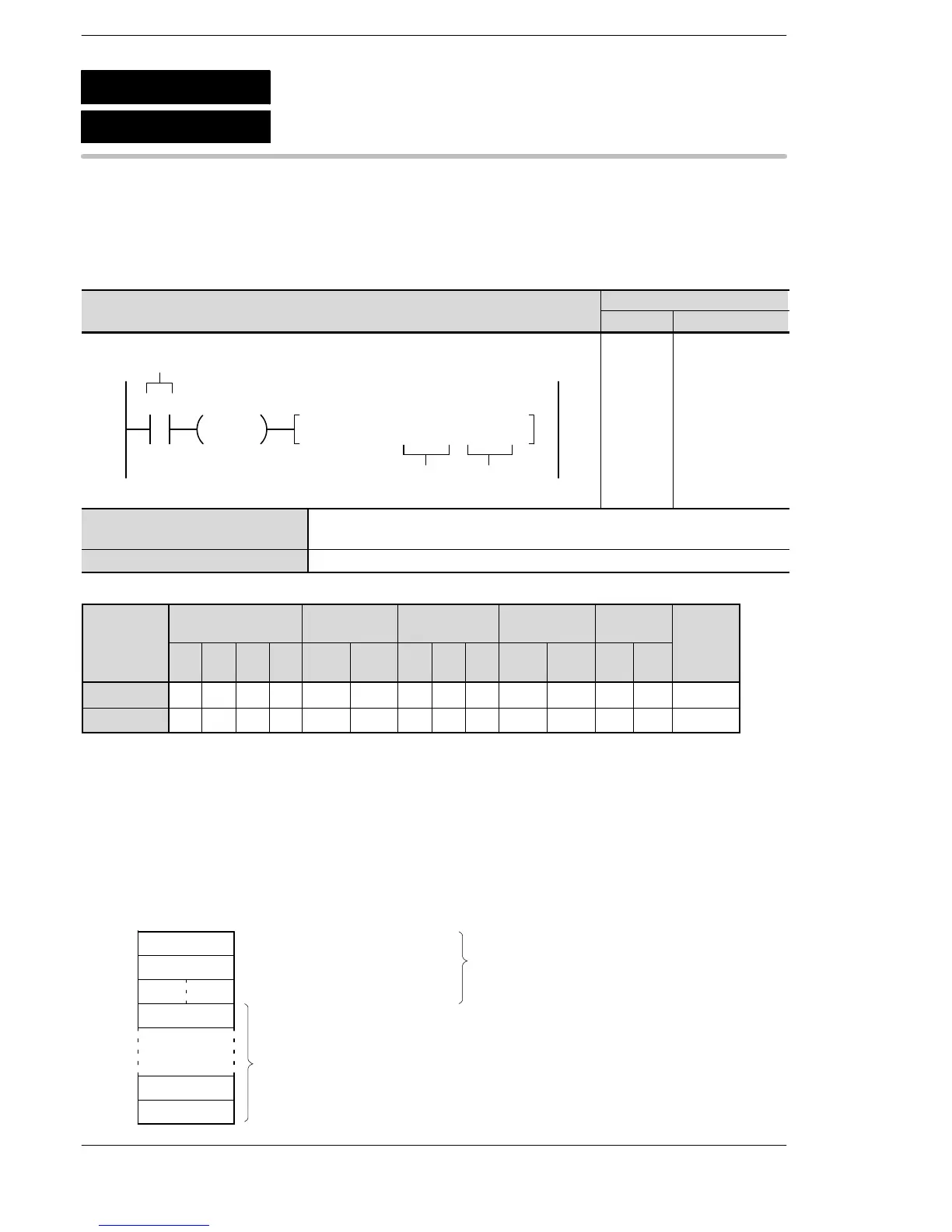
Outline Defines the FIFO buffer conditions.
For the FP0R/FPΣ/FP−X/FP0/FP−e, the P type high−level instruction
“P115 (PFIFT)” is not available.
Program example
modifier
n A A A A A A A A A A A A A A
D N/A A A A A A A A A N/A N/A N/A N/A A
(*1) This cannot be used with the FP0R, FPΣ and FP−X.
(*2) With the FP0R, FPΣ,FP−X, FP2, FP2SH, and FP10SH, this is I0 to IC.
(*3) With the FP0R, FPΣ,FP−X, FP2, FP2SH, and FP10SH, this is ID.
Explanation of example
When the execution condition (trigger) R0 is on, the area headed by DT0 is defined in the FIFO buffer area.
The size of the FIFO buffer (K256) is stored in DT0, the number of data items stored is stored in DT1 (with a
default value of K0), and the FIFO pointer (with a default value of H0000) is stored in DT2.
When n = K256, the 256 words from DT3 to DT258 are defined as the data storage area.
K0
0
K256DT0
15 0
Memory size of FIFO buffer (n)
Number of stored data items (words)
FIFO pointer
DT1
DT2
DT3
DT257
DT258
Data storage area
(256 words)
0
Transmission is enabled by the F0 (MV)
instruction (overwriting is possible).
F115
P115
(PFIFT)
(FIFT)
FIFO buffer definition
A: Available
N/A: Not Available





 To Next Page