Boolean
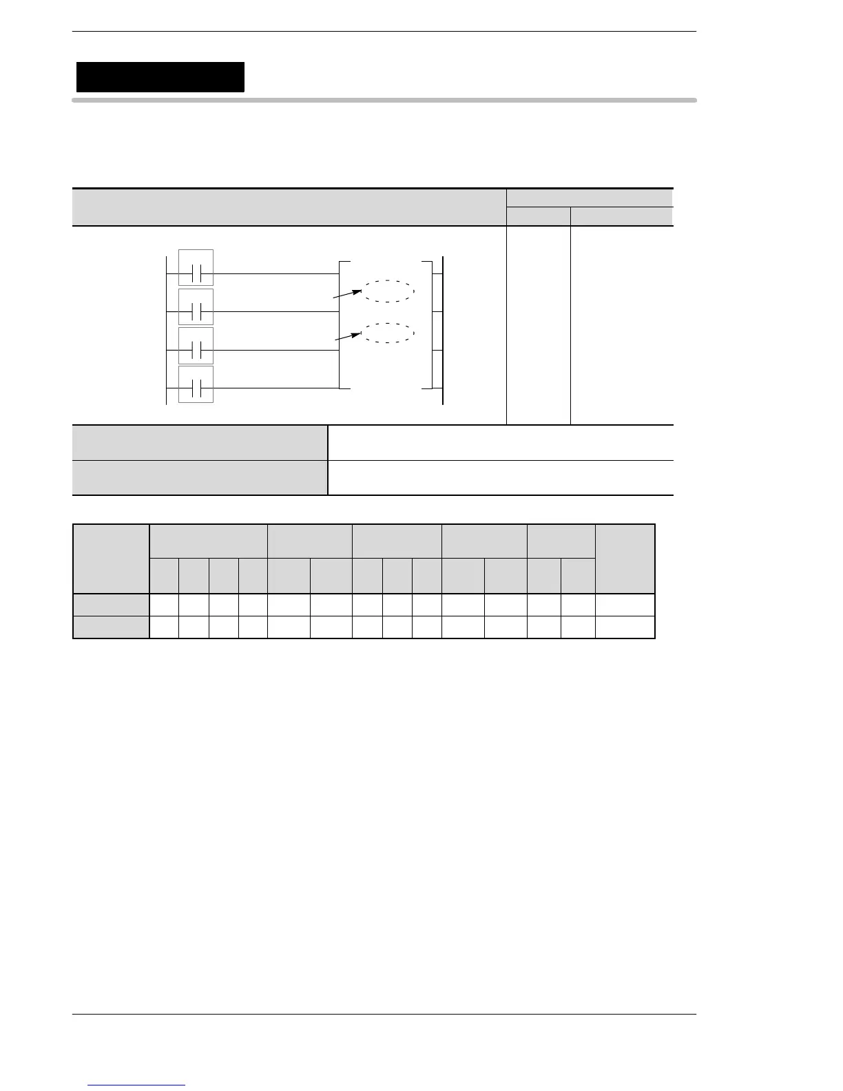
Ladder Diagram
Address Instruction
R1
F119 LRSR
R0
50
Left/right input
(on: left, off: right)
51
R2
Shift input
52
DT 0
DT 9
Data input
D1
D2
Reset input
53
R3
50
51
52
53
54
ST R 0
ST R 1
ST R 2
ST R 3
F119 (LRSR)
DT 0
DT 9
D1 Starting 16-bit area whose one bit is shifted to the left or to the
right
D2 Ending 16-bit area whose one bit is shifted to the left or to the
right
Operands
modifier
D1 N/A A A A A A A A A N/A N/A N/A N/A N/A
D2 N/A A A A A A A A A N/A N/A N/A N/A N/A
(*1) This cannot be used with the FP0 and FP−e.
(*2) This cannot be used with the FP0, FP−e, FP0R, FPΣ, FP−X.
Left/right shift register
F119
(LRSR)
A: Available
N/A: Not Available






 To Next Page