High−level Instructions
3 − 282
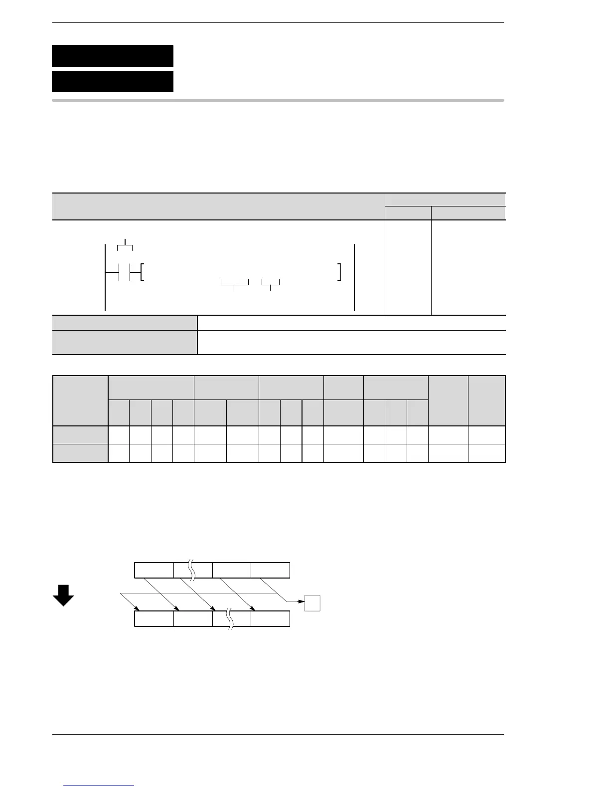
Outline Rotates a specified number of bits in specified 32-bit data to the right.
For the FP0R/FPΣ/FP−X/FP0/FP−e, the P type high−level instruction
“P125 (PDROR)” is not available.
Program example
Boolean
Ladder Diagram
Address Instruction
F125 DROR, DT10, K410
R0
nD
Trigger
10
11
ST R 0
F125 (DROR)
DT 10
K4
D Lower 16-bit area of 32-bit data
n 16-bit equivalent constant or 16-bit area to specify number of bits to be rotated
Range of n: K0 to K255 (H0 to HFF)
Operands
Relay Timer/Counter Register
Index
register
Constant
Inde
er
Operand
WX WY WR WL SV EV DT LD
FL
(*1)
I K H f
device
D N/A A A A A A A A A A N/A N/A N/A A N/A
n A A A A A A A A A A A A N/A A N/A
(*1) This cannot be used with the FP0R, FPΣ and FP−X.
Explanation of example
Rotates 4 bits in data registers DT11 and DT10 to the right when trigger R0 turns on.
When 4 bits are rotated to the right, the data in bit position 3 is transferred to special internal relay R9009
(carry flag).
1010 1100 1011
31 0
1011
[DT11,DT10]
1010
[DT11, DT10]
1100
CY
28 27 8 7 4 3
R0: on
···
F125
P125
(PDROR)
(DROR)
32-bit data right rotation
vailable
N/A: Not Available
Phone: 800.894.0412 - Fax: 888.723.4773 - Web: www.clrwtr.com - Email: info@clrwtr.com





 To Next Page