WX WY WR SV EV DT I K H
modifier
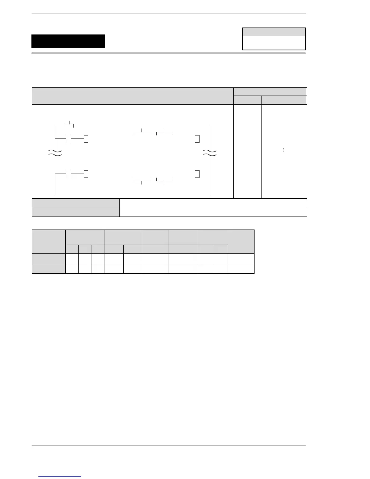
D1 A A N/A N/A N/A N/A N/A N/A N/A A
D2 A A N/A N/A N/A N/A N/A N/A N/A A
Explanation of example
Updates external input relays WX0 (X0 to XF) immediately when the execution condition (trigger) R10 turns
on and updates external output relays WY0 (Y0 to YF) immediately when the execution condition (trigger)
R20 turns on.
Description
Updates the external inputs X and external outputs Y specified by D1 and D2 immediately even in the
program execution stage.
Refreshing (Updating) initiated by the F143 (IORF) instruction is done only for the control unit.
With input refreshing (updating), WX0 should be specified for [D1] and [D2].
With output refreshing (updating), WY0 should be specified for [D1] and [D2].
The allowable I/O range for the partial update varies depending on the models.
FP0/FP0R/FP−e/FPΣ/FP−X
F143
(IORF)
Partial I/O update
Availability
FP0/FP0R/FP−e/
FPΣ/FP−X
A: Available
N/A: Not Available












 To Next Page