WX WY WR WL SV EV DT LD FL IX IY K H
modifier
D1 N/A N/A N/A N/A N/A N/A N/A N/A N/A N/A N/A A A A
D2 N/A N/A N/A N/A N/A N/A N/A N/A N/A N/A N/A A A A
Explanation of example
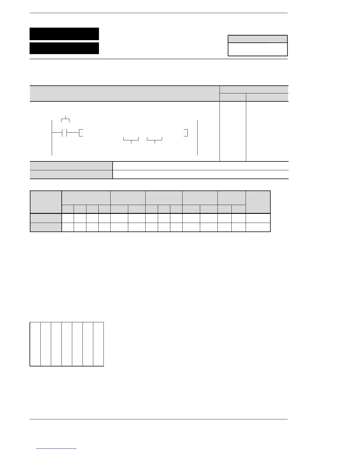
Updates the input and output relay of word no. 0 to 1 (2 words, 32 points) immediately when the trigger R10
turns on.
When the configuration shown below is being used:
When the instruction is executed, the WX0 (X0 to XF) input processing and the WY1 (Y10 to Y1F) output
processing are carried out.
Outline Updates specified partial I/O points.
0 1 2 3 4 (Slot no.)
Power supply unit
CPU
16−point input unit
16−point output unit
FP2/FP2SH/FP10SH
F143
P143
(PIORF)
(IORF)
Partial I/O update
Availability
FP2/FP2SH/FP10SH
A: Available
N/A: Not Available












 To Next Page