High−level Instructions
3 − 357
2
Specifying the relay station
S+1 should be used to specify only the specified amount of depth, while (S1+3) is used to specify
depth 2 for the same item, and (S1+4) is used to specify depth 3.
Route No. of relay destination in depth 1: H01 to H08
S1+2:
Unit No. of relay source in depth 1: H01 to H40 (1 to 64)
3
Specifying the remote station
This should be specified right after the specification of the relay station.
Specifies H00
S1+n:
Unit No. of remote station: H01 to H40(1 to 64)
(n = depth + 2)
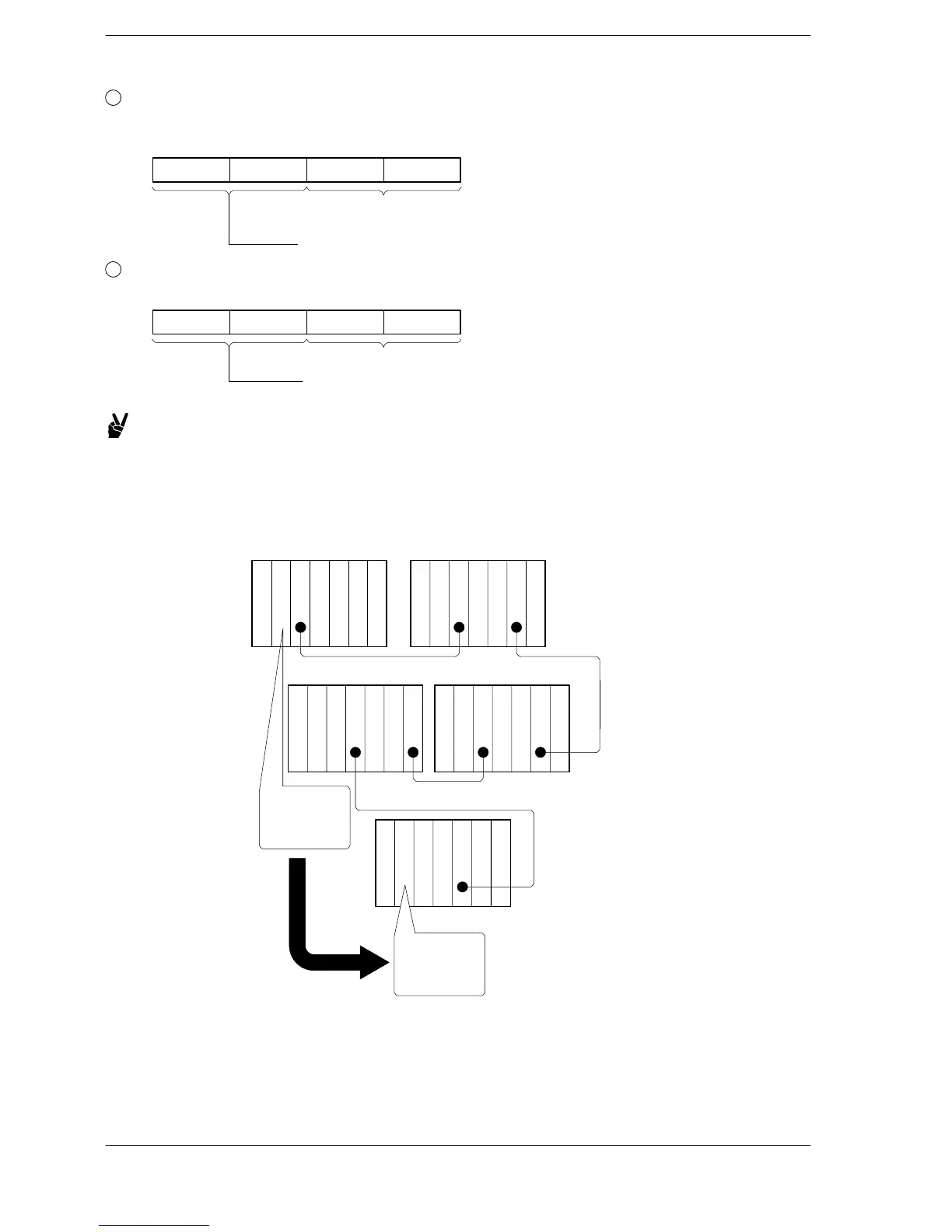
Example: When using the program example shown on page 3 − 339
In this example, the 5 words of data from DT20 to DT24 of the local
station (CPU1) are sent to DT100 and subsequent addresses of
the CPU (CPU5) shown below.
No.2
No.4
No.16
No.10
4321
3211
321
DT100
to
DT104
DT20
to
DT24
No.1
Power
CPU 1
Link
Power
CPU 2
Link
Link
Link
Power
CPU 4
Power
CPU 3
Link
Link
Link
Power
CPU 5
Link
Connection diagram












 To Next Page