High−level Instructions
3 − 371
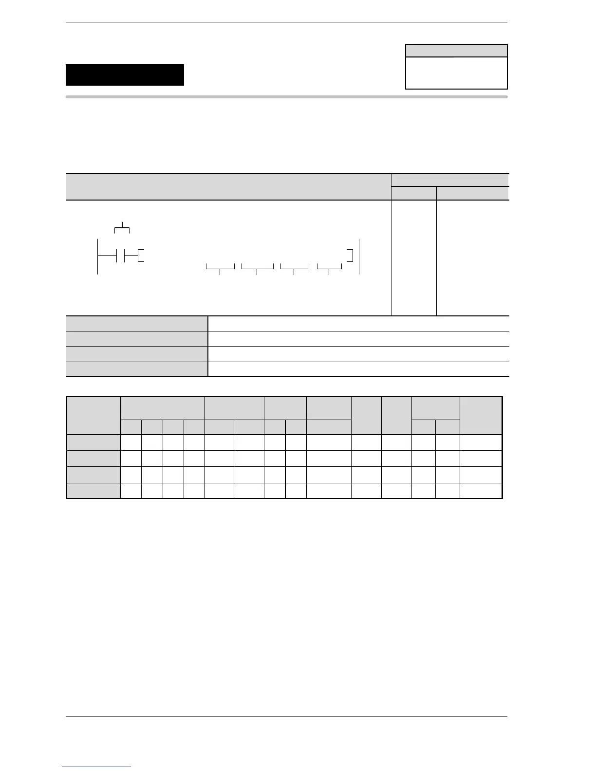
Outline Receives specified data from the serial port of another PLC or computer
to the unit.
Feature: Data can be transmitted with this instruction only.
Program example
Boolean
Ladder Diagram
Address Instruction
10
F146 RECV, DT10 , H10 , H20 , DT50
S1
S2
Trigger
R0
N
D
10
11
ST R 0
F146 (RECV)
DT 10
H10
H20
DT 50
S1 Starting 16−bit area for storing control data
S2 Specification of MODBUS address
N No. of received data
D Starting 16−bit area address for storing data received
Operands
O
K H
modifier
S1 A A A A A A A A N/A A A A A A
S2 A A A A N/A N/A A A N/A N/A N/A A A N/A
N N/A A A A A A A A N/A N/A N/A A A A
D N/A A A A A A A A N/A N/A N/A N/A N/A A
(*1) I0 to ID
(*2) This instruction is available only for FP0R/FPΣ V3.20 or later/FP −X V.250 or later.
Description
The data of the volume specified by [N] is received form the MODBUS address specified by [S2] with the
specification of the transmission port, transmission command (1 or 2) and destination unit number, and
stored in the operation memory specified by [D].
MODBUS commands are transmitted. (MODBUS commands 01, 02, 03 and 04)
The feature is that data can be transmitted with this instruction only.
FPΣ/FP−X/FP0R
F146
(RECV)
Data receive
(MODBUS master mode II: Type
directly specifying MODBUS address)
Availability
FP0R
FP−X: Ver. 2.50
FPΣ: Ver. 3.20
A: Available
N/A: Not Available












 To Next Page