High−level Instructions
3 − 387
Explanation of example
The ASCII codes stored in data registers DT0 to DT5 are output through word external output relay WY0
when trigger R10 turns on.
ASCII HEX code
Data register
ASCII character
DT5
LF
DT4
JI
DT3
G
DT2
FE
0D 0A 4A 49 48 47 46 45
DT1
DC
DT0
BA
44 43 42 41
Destination
Source: ASCII code for 12 character A, B, C, D, E, F, G, H, I and J
R10: on
WY0
ASCII codes
Y9 to YF: not used
Control data for printer
YF YE YD YC YB YA Y9 Y8 Y7 Y6 Y5 Y4 Y3 Y2 Y1 Y0
Y0 to YF: for data signals of printer
(Y0 to Y7 correspond to DATA1 to DATA8 of printer.)
Y8: for strobe signal of printer
H
C
R
Description
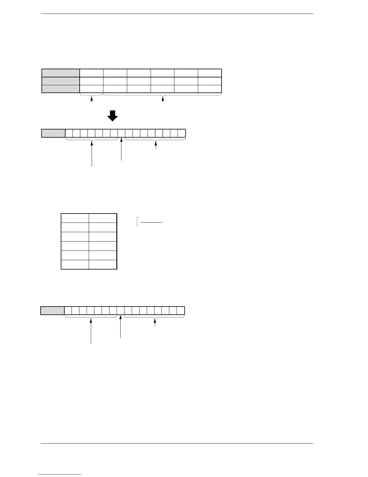
Outputs the ASCII codes for 12 characters stored in the 6-word area specified by S through the word external
output relay WY specified by D.
S → WY
S+1
S+2
S+3
S+4
S+5
15 0
D1 to D8
STROBE
If the specified output is connected to a commercial printer, the characters corresponding to the output ASCII
code are printed.
Only bit positions 0 to 8 of WY are used in the actual printout.
WY0
Y9 to YF: not used
YFYE YD YC YB
YA
Y9 Y8 Y7 Y6 Y5 Y4 Y3 Y2 Y1 Y0
Y0 to YF: for data signals of printer
(Y0 to Y7 correspond to DATA1 to DATA8 of printer.)
Y8: for strobe signal of printer
ASCII code is output in order starting from the lower byte of the starting area.
Be sure to set the control code (LF and C
R
) for the printer as the final word of the data.
Three scans are required for 1 character constant output. Therefore, 37 scans are required until 12 character
constants are output. (See “Time chart”)












 To Next Page