High−level Instructions
3 − 398
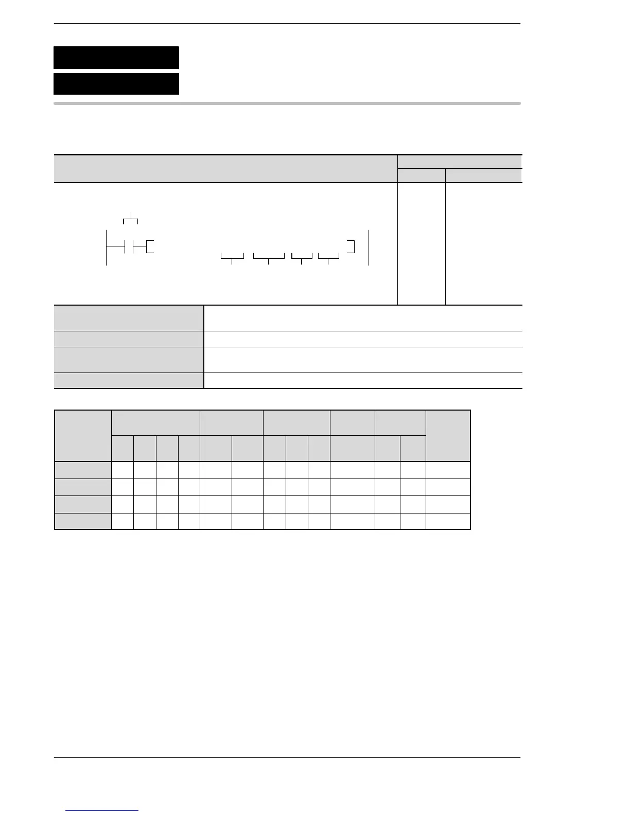
Outline Writes data into the shared memory in an intelligent unit.
Program example
Boolean
Ladder Diagram
Address Instruction
10
F151 WRT, H 0, DT 10, K 5, K 0
S1
S2
Trigger
R10
n
D
10
11
ST R 10
F151 (WRT)
H0
DT 10
K5
K0
S1 16-bit equivalent constant for specifying the bank number in the shared
memory of the intelligent unit.
S2 Starting 16-bit area address for storing data written in the shared memory.
n 16-bit equivalent constant for specifying the number of words written in the
shared memory.
D Starting 16-bit area address for storing data written (destination data address).
Operands
Relay Timer/Counter Register
Index
register
Constant
Inde
Operand
WX WY WR WL SV EV DT LD
FL
(*1)
I K H
modifier
S1 N/A N/A N/A N/A N/A N/A N/A N/A N/A N/A A A A
S2 A A A A A A A A A N/A N/A N/A A
n N/A N/A N/A N/A N/A N/A N/A N/A N/A N/A A A A
D N/A N/A N/A N/A N/A N/A N/A N/A N/A N/A A A A
(*1) This cannot be used with the FPΣ.
F151
P151
(PWRT)
(WRT)
Data write into intelligent unit
A: Available
N/A: Not Available
Phone: 800.894.0412 - Fax: 888.723.4773 - Web: www.clrwtr.com - Email: info@clrwtr.com












 To Next Page