High−level Instructions
3 − 403
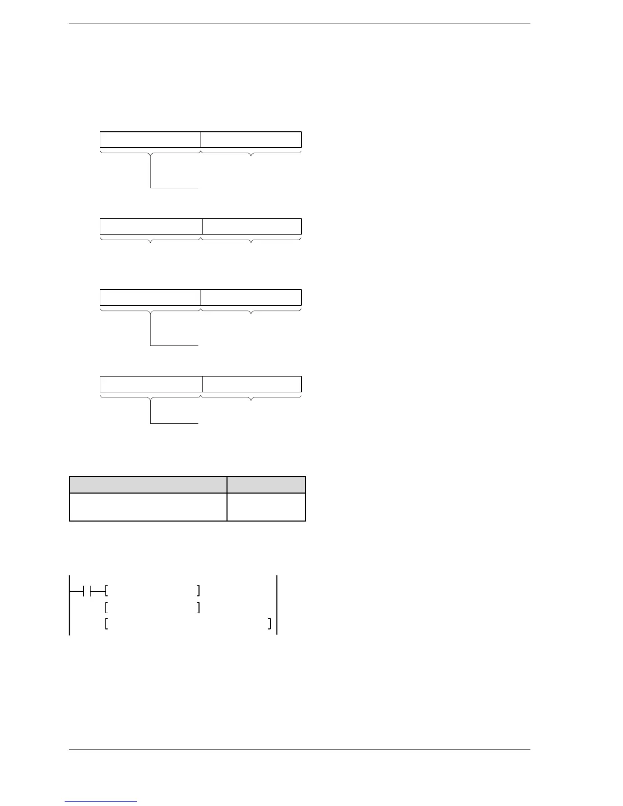
Specifying control data (S1+1 and S1)
Specify the master station number and the slave station number with S1, and the slot number of the target
intelligent unit with S1+1.
Intelligent unit without bank
Upper byte Lower byte
Upper byte Lower byte
Slave station No.H01 to H20 (1 to 32)
Master station No. H01 to H04 (1 to 4)
H00 Slot No.H00 to H1F
S1
S1+1
Intelligent unit with bank
Upper byte Lower byte
Upper byte Lower byte
Slave station No.H01 to H20 (1 to 32)
Master station No. H01 to H04 (1 to 4)
Bank No.H00 to HFF
Slot No.H00 to H1F
S1
S1+1
Reference: Intelligent unit with bank
Name Order No.
FP3 expansion data memory unit
AFP32091
AFP32092
Example of setting
When specifying the intelligent unit installed in slot number 0 of the No. 5 slave station on the path of the No. 1
master station, using the program example on page 3 − 401, the program will be structured as follows.
F0 MV, H0105, DT0
R10
F0 MV, H 0 , DT1
F152 RMRD, DT0, K0, K10, DT10
The control data is specified as shown below.
DT0=H0105 (master station No.1 and slave station No.5)
DT1=H0 (slot 0)












 To Next Page