High−level Instructions
3 − 407
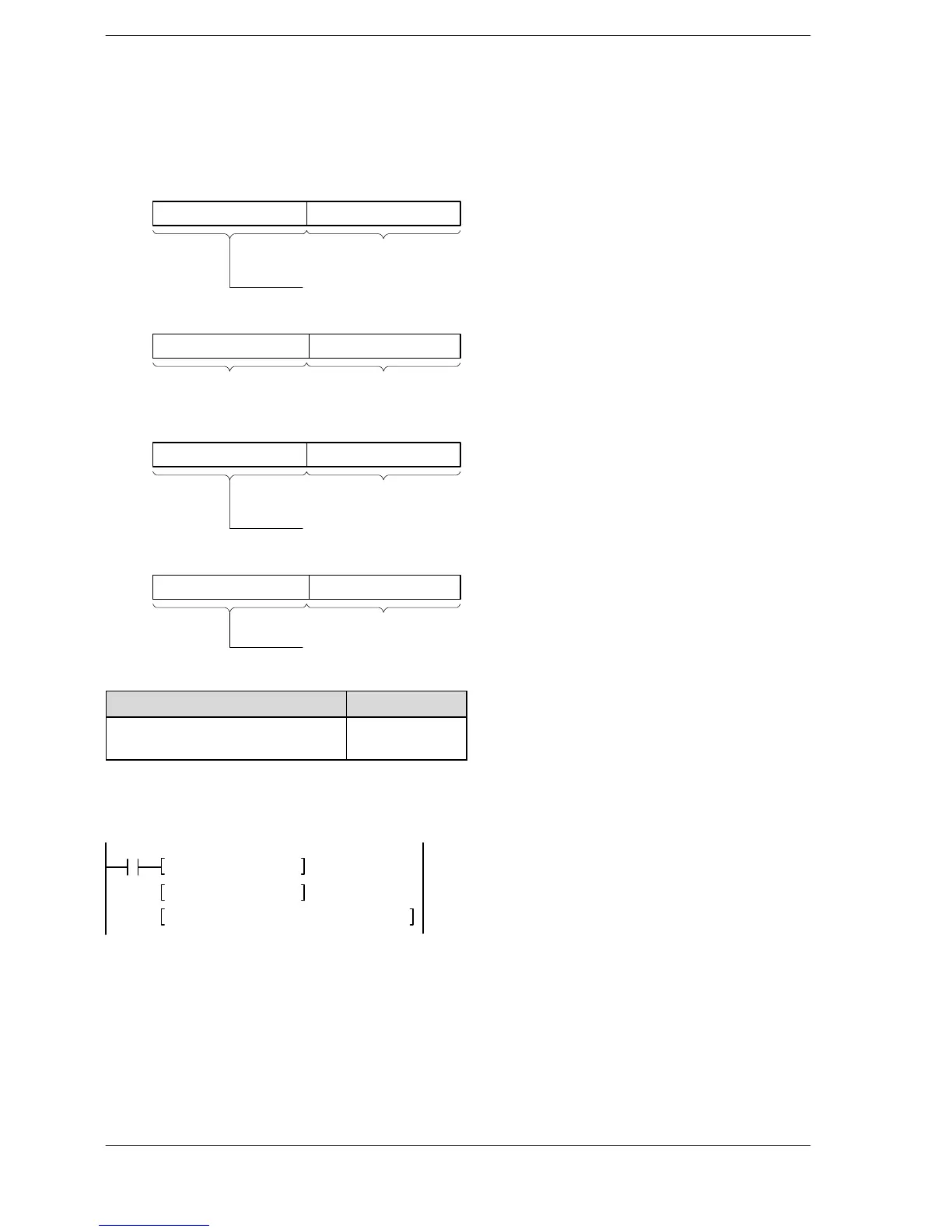
Specifying control data (S1+1 and S1)
Specify the master station number and the slave station number with S1, and the memory of the target
intelligent unit with S1+1.
Intelligent unit without bank
Upper byte Lower byte
Upper byte Lower byte
Slave station No.: H01 to H20 (1 to 32)
Master station No.: H01 to H04 (1 to 4)
H00 Slot No: H00 to H1F
S1
S1+1
Intelligent unit with bank
Upper byte Lower byte
Upper byte Lower byte
Slave station No.: H01 to H20 (1 to 32)
Master station No.: H01 to H04 (1 to 4)
Bank No.: H00 to HFF
Slot No.: H00 to H1F
S1
S1+1
Reference: Intelligent unit with bank
Name Order No.
FP3 expansion data memory unit
AFP32091
AFP32092
Example of setting
When specifying the intelligent unit installed in slot number 2 of the No. 10 slave station on the path of the No.
2 master station, using the program example on page 3 − 405, the program will be structured as follows.
F0 MV, H020A, DT0
R10
F0 MV, H 2, DT1
F153 RMWT, DT0, DT250, K20, K500
The control data is specified as shown below.
DT0=H020A (master station No.2, slave station No.10)
DT1=H2 (slot 2)












 To Next Page