High−level Instructions
3 − 420
Outline This is used to send data to or receive data from an external device
through the specified RS232C port.
Program example
Boolean
Ladder Diagram
Address Instruction
Trigger
S n
10
R0
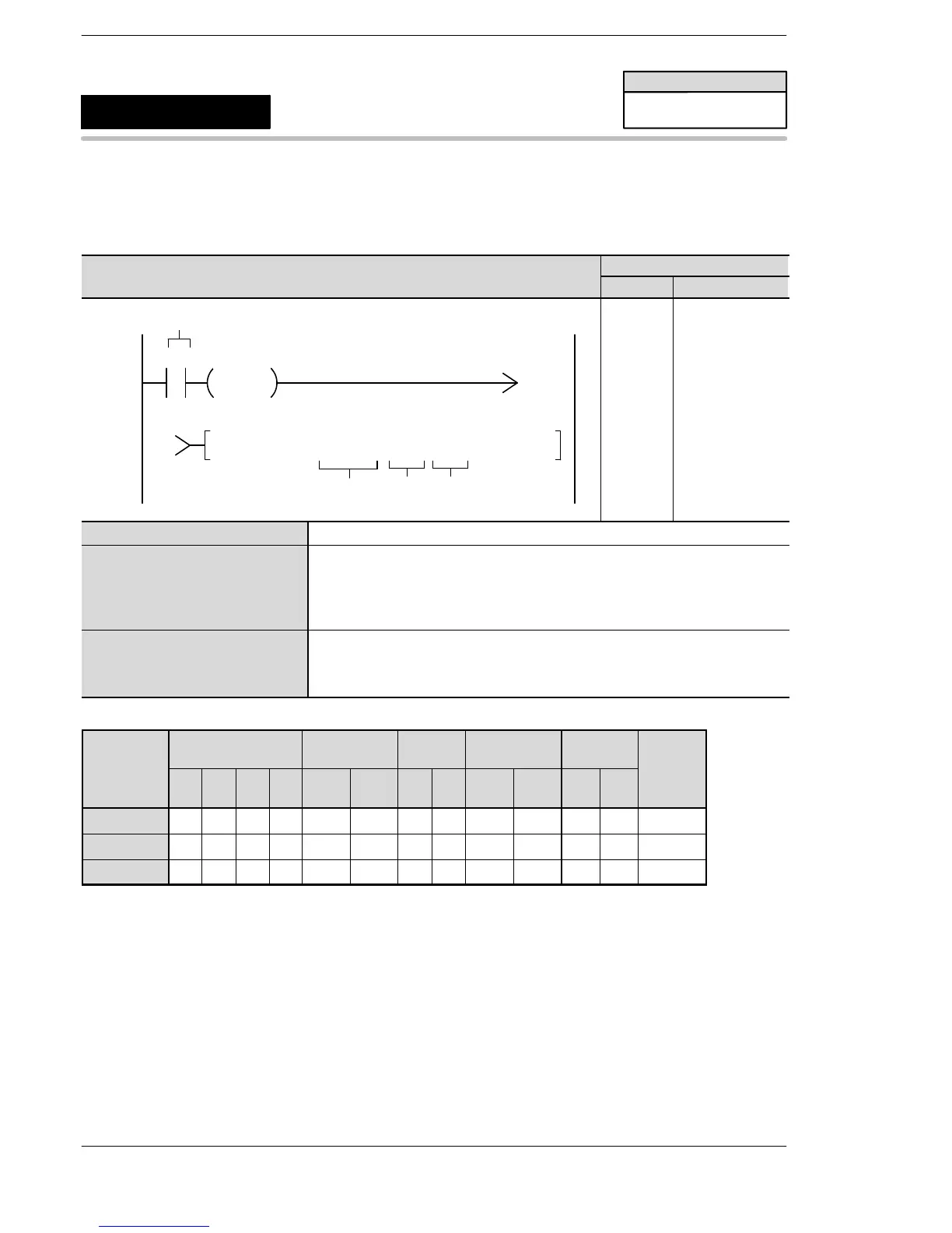
F159 MTRN, DT 100, K 8, K 1
1
1
DF
D
10
11
12
ST R 0
DF
F159 (MTRN)
DT 100
K8
K1
S Starting area of data table (data register)
n Area for storing the number of bytes of data to be transmitted, or constant data.
When the value is positive, an end code is added.
When the value is negative, an end code is not added.
When the value is H8000, the transmission mode of the RS232C port is
changed.
D Port for transmitting data (K0, K1, K2)
K0: TOOL port (FPΣ 32k, FP−X)
K1: COM1 Port (FP0R: COM Port)
K2: COM2 Port
Operands
modifier
S N/A N/A N/A N/A N/A N/A A N/A N/A N/A N/A N/A A
n A A A A A A A A A A A A A
D N/A N/A N/A N/A N/A N/A N/A N/A N/A N/A A N/A A
(*1) I0 to ID.
FPΣ/FP−X/FP0R
F159
(MTRN)
Serial data communication
Availability
FPΣ/FP−X/FP0R
A: Available
N/A: Not Available












 To Next Page