High−level Instructions
3 − 422
Programming and operation during transmission
To execute transmission, write the data to be transmitted to the data table and specify with an F158(MTRN)
instruction.
Use an F0(MV) or F95(ASO) instruction to write the data to be transmitted to the transmission data storage
area specified in “S”.
− Do not include an end code in the transmission data. An end code is added automatically.
− When “yes” is specified for the start code in system register 413 or 414, do not add a start code to the
transmission data. A start code is added automatically.
− The maximum number of transmission bytes “n” is 2048.
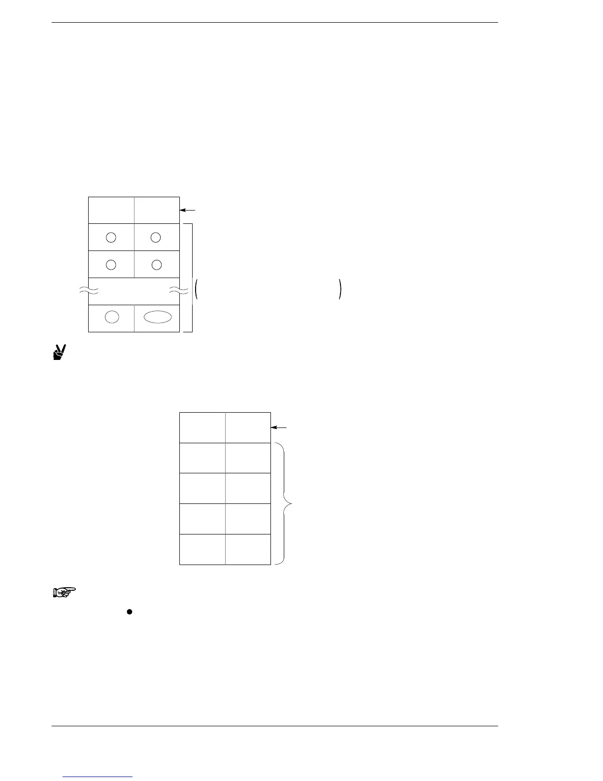
Data table for transmission
This is used as a data table for transmission, starting at the data register specified in “S”.
[S]
At the beginning of transmission,
nothing is set.
At the end of transmission, “0” is set.
[S+1]
[S+2]
[S+n]
12
34
2n
2n−1
Transmission data storage area
The circled numbers indicate the
order of transmission.
Example:
Transmitting the eight characters A, B, C, D, E, F, G, H (8 bytes
of data)
This example uses DT100 to DT104 as the data table.
DT100
When transmission begins: Nothing is set.
When transmission ends: Cleared to 0.
DT101
DT102
DT104
H42
(B)
H41
(A)
H44
(D)
H43
(C)
H48
(H)
H47
(G)
Data is transmitted
in order from the
lower−order byte.
DT103
H46
(F)
H45
(E)
K8
Data table before transmission
Notes
When using a RS232C × 1 ch type communication cassette,
transmission does not take place until CS (Clear to Send)
turns on. If you are not going to connect to the other device,
connect to RS (Request to Send). (FPΣ,FP−X C14)
As for the FP−X C30/C60, it depends on the settings. Refer to
the FP−X Manual.
*1. With the FP0R, FPΣ V3.10 or later, FP−X V2.50 or later, the
number of transmitted data is set.
FPΣ/FP−X/FP0R












 To Next Page