High−level Instructions
3 − 458
Example of setting 1
[Condition]
(1) Target values: 4 points Position output from R10
(2) Each taget value is as the table below.
Position output
Target value
1 (R11) 2000
2 (R12) 4000
3 (R13) 8000
4 (R14) 10000
(3) The maximum value is 14000 pulses.
(4) The elapsed value of the high−speed counter is cleared to 0 before starting the position output.
Program
(DF)
F165 CAM0, DT100
R3
F1 DMV , H 10, DT100
F1 DMV , H 1, DT102
F1 DMV , H 4, DT104
F1 DMV , K 2000, DT106
F1 DMV , K 4000, DT108
F1 DMV , K 8000, DT110
F1 DMV , K 10000, DT112
F1 DMV , K 14000, DT114
F1 DMV , K 0, DT90300
R9013
Start of cam control
Specification of high−speed counter channel 0
Specification of internal relay word No.
4−point output
Target value 1
Max. target value
Reset of elapsed value
Target value 2
Target value 3
Target value 4
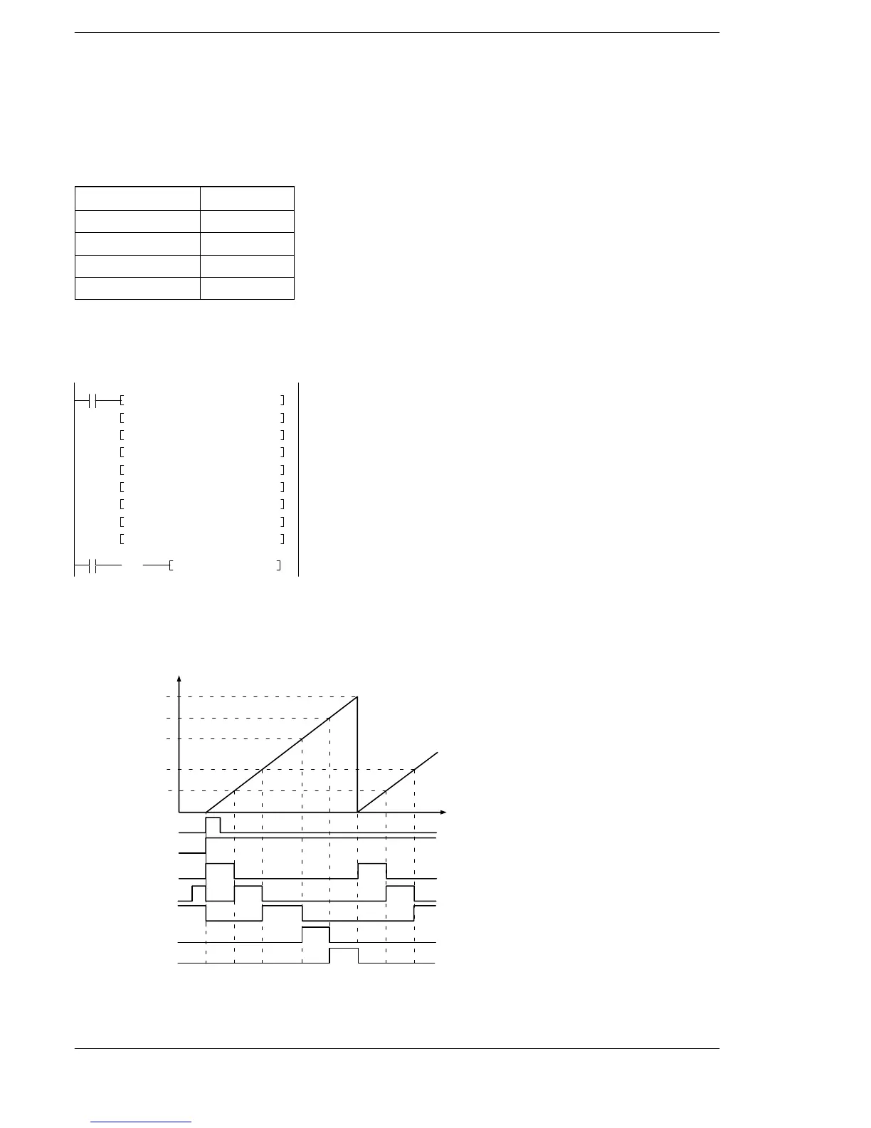
Explanation of program operation
When adding elapsed values with the maximum target value
When the internal relay R3 is on, the operation is as follows.
K14000
K10000
K8000
K4000
K2000
R3
R9110
R10
R11
R12
R13
R14
Elapsed value of high−speed counter
Max. target value
Time
FP0R












 To Next Page