WX WY WR SV EV DT IX IY K H
modifier
S N/A N/A N/A N/A N/A A N/A N/A N/A N/A A
n N/A N/A N/A N/A N/A N/A N/A N/A A A N/A
Description
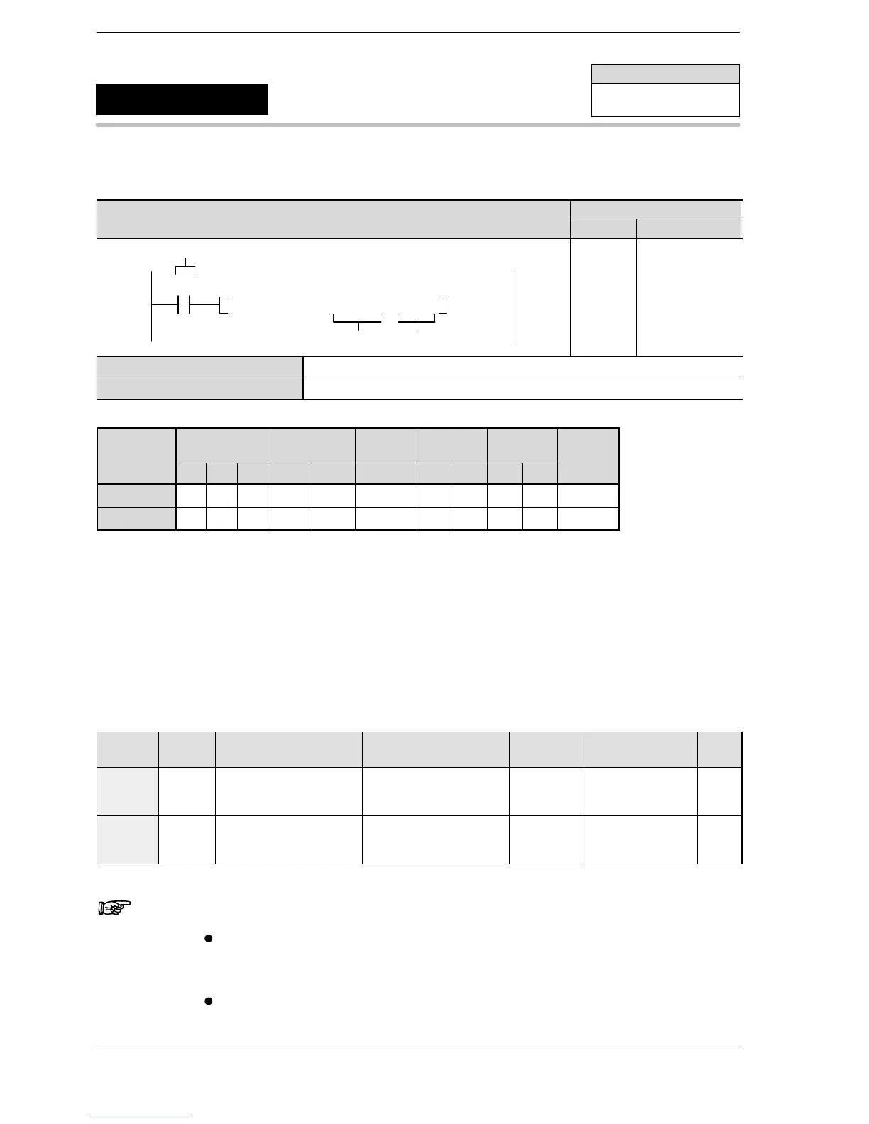
When the corresponding control flag is off and the execution condition (trigger) is in the on state, a pulse is
output from the specified output (Y0 or Y1).
The control code, initial speed, maximum speed, and acceleration/deceleration time are specified by a user
program with a data table as shown on the following page.
The frequency is switched by the acceleration/deceleration time specified for changing from the initial speed
to the maximum speed. During deceleration (normally 30 steps), the frequency is changed based on the
same slope as during acceleration.
Table of areas used
Channel
no.
Control
flag
Elapsed value area Target value area
Directional
output
Near home input
Home
input
ch0 R903A
DT9044, DT9045
(For FP0 T32,
DT90044, DT90045)
DT9046, DT9047
(For FP0 T32,
DT90046, DT90047)
Y2
DT9052 bit2
(For FP0 T32,
DT90052)
X0
ch1 R903B
DT9048, DT9049
(For FP0 T32,
DT90048, DT90049)
DT9050, DT9051
(For FP0 T32,
DT90050, DT90051)
Y3
DT9052
(For FP0 T32,
DT90052)
X1
Notes
When this instruction is used, the setting for the channel
corresponding to system register 400 should be set to
“High−speed counter not used”.
By performing rewrite during RUN during pulse output, more
than the set number of pulses may be output.
FP0/FP−e
Positioning control
(home position return)
5
F168
(SPD1)
Availability
FP0/FP−e
A: Available
N/A: Not Available












 To Next Page