High−level Instructions
3 − 494
The control code, initial speed, maximum speed, acceleration/deceleration time, and target value are
specified by creating the data table “S” to “S+11” on the following page using the user program.
The frequency is changed using the specified acceleration/deceleration time from the initial speed to the
maximum speed. During deceleration, the frequency is changed based on the same slope as during
acceleration.
If the frequency is set to 50 kHz or more, specify a duty of 1/4 (25%).
If the frequency for ch2 or ch3 of FP−X Tr type is set to 10kHz or more, specify a duty of 1/4 (25%).
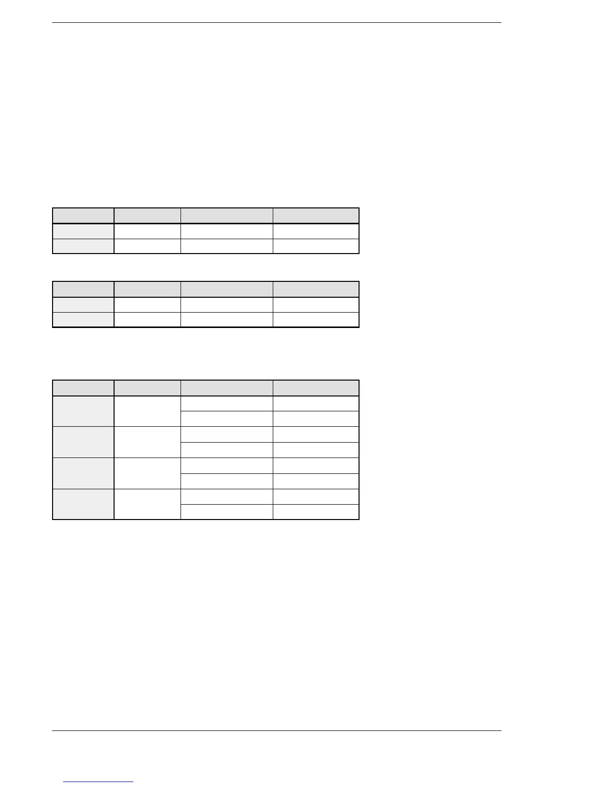
Table of areas used
For FP Σ
Channel no. Control flag Elapsed value area Target value area
ch0 R903A DT90044, DT90045 DT90046, DT90047
ch2 R903C DT90200, DT90201 DT90202, DT90203
For FP−X Ry type
Channel no. Control flag Elapsed value area Target value area
ch0 R911C DT90348, DT90349 DT90350, DT90351
ch1 R911D DT90352, DT90353 DT90354, DT90355
Note) Ch1 cannot be used for C14R.
For FP−X Tr type
Channel no. Control flag Elapsed value area Target value area
DT90361 DT90363
Note) There is no ch3 for C14T and C14TD.
Note) The pulse I/O cassette (AFPX−PLS) cannot be installed on the FP −X Tr type.
Note) Use the ch2 and ch3 at up to 20 kHz.
FPΣ/FP−X












 To Next Page