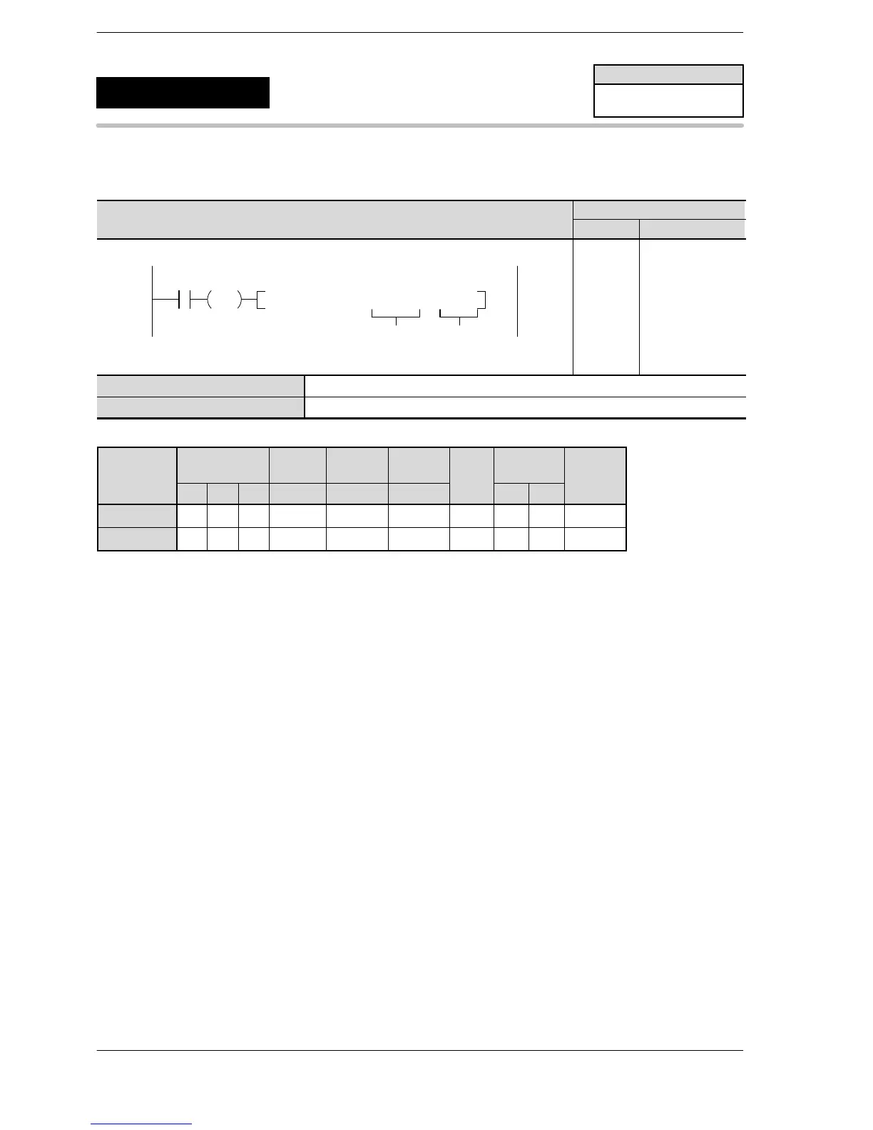
K H
modifier
S N/A N/A N/A N/A A N/A N/A N/A N/A A
n N/A N/A N/A N/A N/A N/A N/A A A N/A
(*1) I0 to ID
Description
When the trigger is on, pulses are output from the specified channels.
The control code, initial speed, target speed, acceleration time, deceleration time and the target value after
the position control starting input is specified by creating data tables [S] to [S+11] using user progrmas.
When accelerating, the frequency is changed in the acceleration time specified from the initial speed to the
target speed.
The pulse output continues until the position control starting input turns on after reaching the target speed.
After the position control starting input turned on, the pulse output continues up to the target value, and then
decelerates and stops.
For using the position control staring input (X0, X1, X2, X3), set the system register 402.
When decelerating, the frequency is changed in the deceleration time specified from the target speed.
The positioning control can be also started by the control data (bit6) of DT90052.
(e.g.) F0(MV) H140, DT90052
The deceleration stop can be requested by the control data (bit5) of DT90052.
(e.g.) F0(MV) H120, DT90052
When using the same condition as the table used at the preveious startup, the operation can be started at
high speed without calculation.
During the pulse output, the pulse output insturction flag corresponding to channel turns on.
When the deceleration stop is requested during acceleration, deceleration is performed with the same slope
of the deceleration time from the target speed.
In this instruction, the operation is processed giving the acceleration/deceleration time priority.
The initial speed may be corrected to enable accelerating/decelerating within the specified time.
FP0R
Pulse output
(JOG positioning type 0)
5
F171
(SPDH)
Availability
FP0R
A: Available
N/A: Not Available












 To Next Page