High−level Instructions
3 − 536
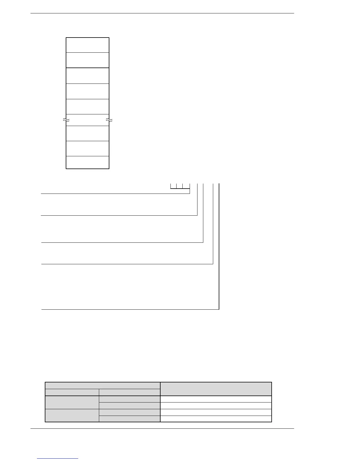
Setting the data tabler
[S]
[S+2]
[S+4]
[S+6]
[S+8]
K0
Frequency 1
Target value 1
(Number of pulses)
Frequency 2
Target value 2
(Number of pulses)
Frequency n
End of table
(Pulse output stops.)
Control code (*1)
[S+2n]
[S+2(n+1)]
[S+2(n+2)]
Target value n
(Number of pulses)
(*2)
(*3)
(*1): Specification of control code “H constant”
Operation mode
0: Incremental Specifies the amount of travel (number of pulses)
1: Absolute Specifies the target value (absolute value)
H □□□
Upper word
0: Fixed
Duty (on width)
0: Duty 1/2 (50%)
1: Duty 1/4 (25%)
Frequency range
0: 1.5 Hz to 9.8 kHz
1: 48 Hz to 100 kHz
2: 191 Hz to 100 kHz
Output method
0: CW (addition counting)
1: CCW (subtraction counting)
2: PLS+SIGN (forward off) (addition counting)
3: PLS+SIGN (reverse on) (subtraction counting)
4: PLS+SIGN (forward on) (addition counting)
5: PLS+SIGN (reverse off) (subtraction counting)
□□□□□
(*2): Frequency (Hz) “K constant”
Frequency range
0: 1.5 Hz to 9.8 kHz [K1 to K9800 (units: Hz)] (Max. error near 9.8 kHz: approx. −0.9 kHz)
* Set “1” to specify 1.5 Hz.
1: 48 Hz to 100 kHz [K48 to K100000 (units: Hz)] (Max. error near 100 kHz: approx. −3 kHz)
2: 191 Hz to 100 kHz [K191 to K100000 (units: Hz)] (Max. error near 100 kHz: approx. −0.8 kHz)
Initial speed: Set ”Frequency 1” to 30 kHz or less.
(*3): Target value (K−2147483648 to K2147483647)
The value of the 32−bit data specified for the target value should be within the range indicated in
the table below.
Specification of control code
ues
Incremental
Addition counting Specifies a positive value.
Subtraction counting Specifies a negative value.
Absolute
Addition counting Specifies a value larger than the current value
Subtraction counting Specifies a value smaller than the current value
FPΣ/FP−X












 To Next Page