[S+10]
Y−axis (FPΣ: CH2, FP−X: CH1)
Target value (Movement distance)
(*4)
[S+12]
X−axis (CH0) component speed
Initial speed Fxmin
[S+14]
X−axis (CH0) component speed
Maximum speed Fxmax
,
are stored here.
[S+23]
Y−axis (FPΣ: CH2, FP−X: CH1) number of
acceleration/deceleration steps
(*7)
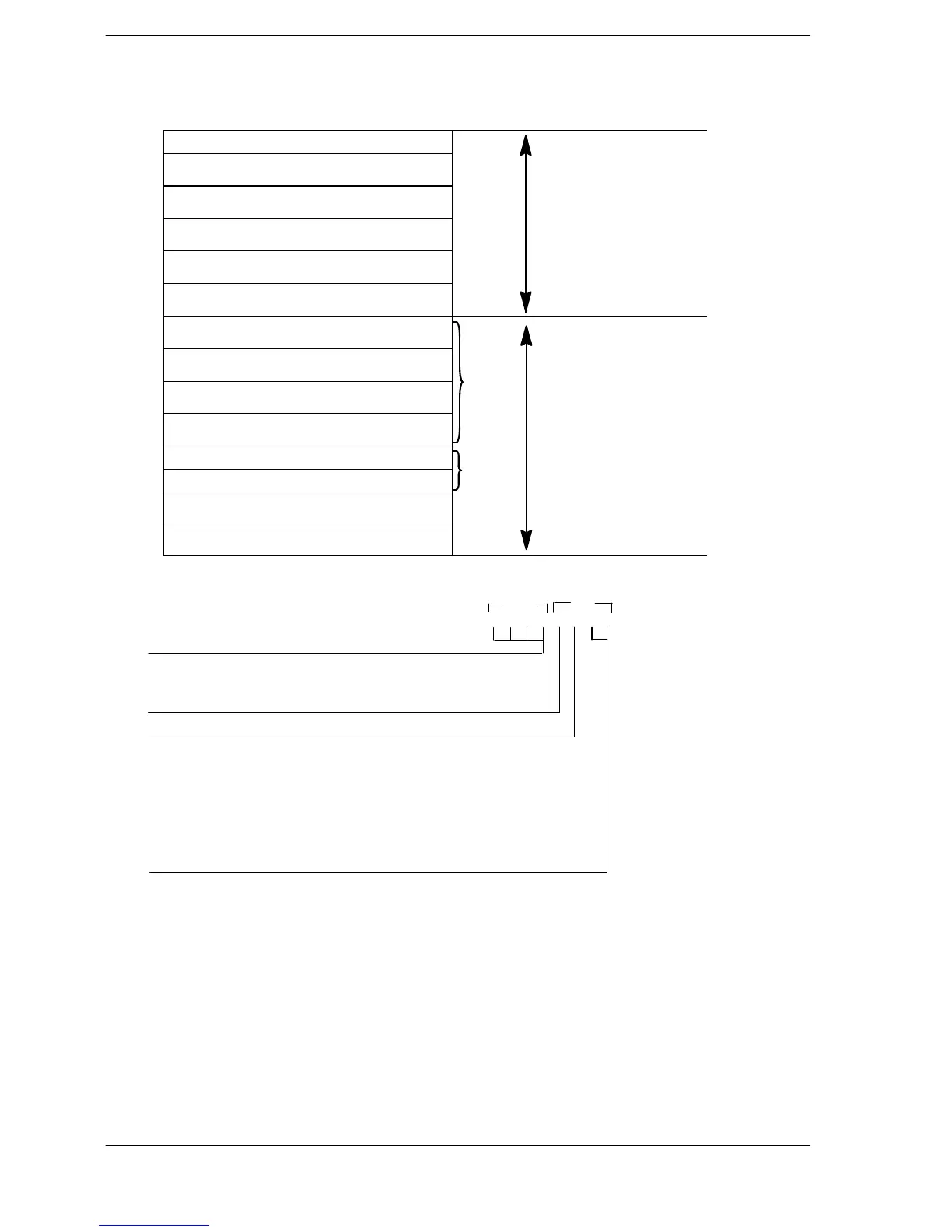
(*1): Specification of control code (specify with H constant)
Operation mode and output method
00: Incremental CW/CCW
02: Incremental PLS + SIGN (forward off / reverse on)
03: Incremental PLS + SIGN (forward on / reverse off)
10: Absolute CW/CCW
12: Absolute PLS + SIGN (forward off / reverse on)
13: Absolute PLS + SIGN (forward on / reverse off)
H □□□□□□□□
0: Fixed
Duty (on width)
0: Duty 1/2 (50%)
1: Duty 1/4 (25%)
0: Fixed
S+1
S
(*2): Composite speed (Initial speed, Maximum speed) (Hz) <K constant>
1.5Hz to 100kHz [K1 to K100000]
However , 1.5Hz is for an angle of 0deg or 90deg only.
Also, specify K1 when specifying 1.5 Hz.
If the component speed drops lower than the minimum speed for each frequency range, then the
speed will become the corrected component speed, so be careful. (See *6)
When simultaneously using a high−speed counter , periodical interrupt or PLC link, do not set to 60kHz
or higher .
If initial speed is set equal to maximum speed, pulses will be output with no acceleration/deceleration.
Set the composite speed so that component speed of each axis is 1.5 Hz or greater .
Composite speed (initial speed): 30 kHz or lower
FPΣ C32T2/FP−X












 To Next Page