High−level Instructions
3 − 553
Outline Pulses are output from channel ch0 and ch2, in accordance with the
parameters in the designated data table, so that the path to the target
position forms an circular.
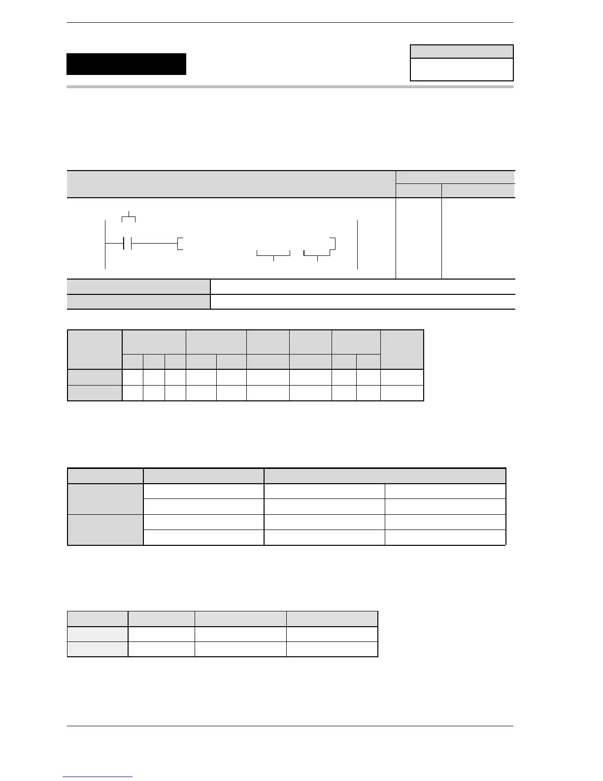
Program example
WX WY WR SV EV DT I K H
modifier
S N/A N/A N/A N/A N/A A N/A N/A N/A A
n N/A N/A N/A N/A N/A N/A N/A A A N/A
Description
Pulses are output from the channel ch0 (for X−axis) and ch2 (for Y−axis) when the corresponding control flag
turns off and the execution condition (trigger) turns on.
For FP Σ
Channel no. Output Output method
ch0 (for X−axis) Y0 CW PLS
Y1 CCW SIGN
ch2 (for Y−axis) Y3 CW PLS
Y4 CCW SIGN
Designate the control code, composite speed, target position and pass position by creating the data table “S”
to “S+11” on the next page with the user program.
Table of areas used
Channel no. Control flag Elapsed value area Target value area
ch0 R903A DT90044, DT90045 DT90046, DT90047
ch2 R903C DT90200, DT90201 DT90202, DT90203
FPΣ
Pulse output
(Circular interpolation)
5
F176
(SPCH)
Availability
FPΣ C32T2, C32T2H
C28P2, C28P2H
A: Available
N/A: Not Available












 To Next Page